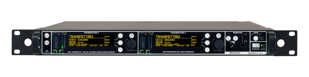
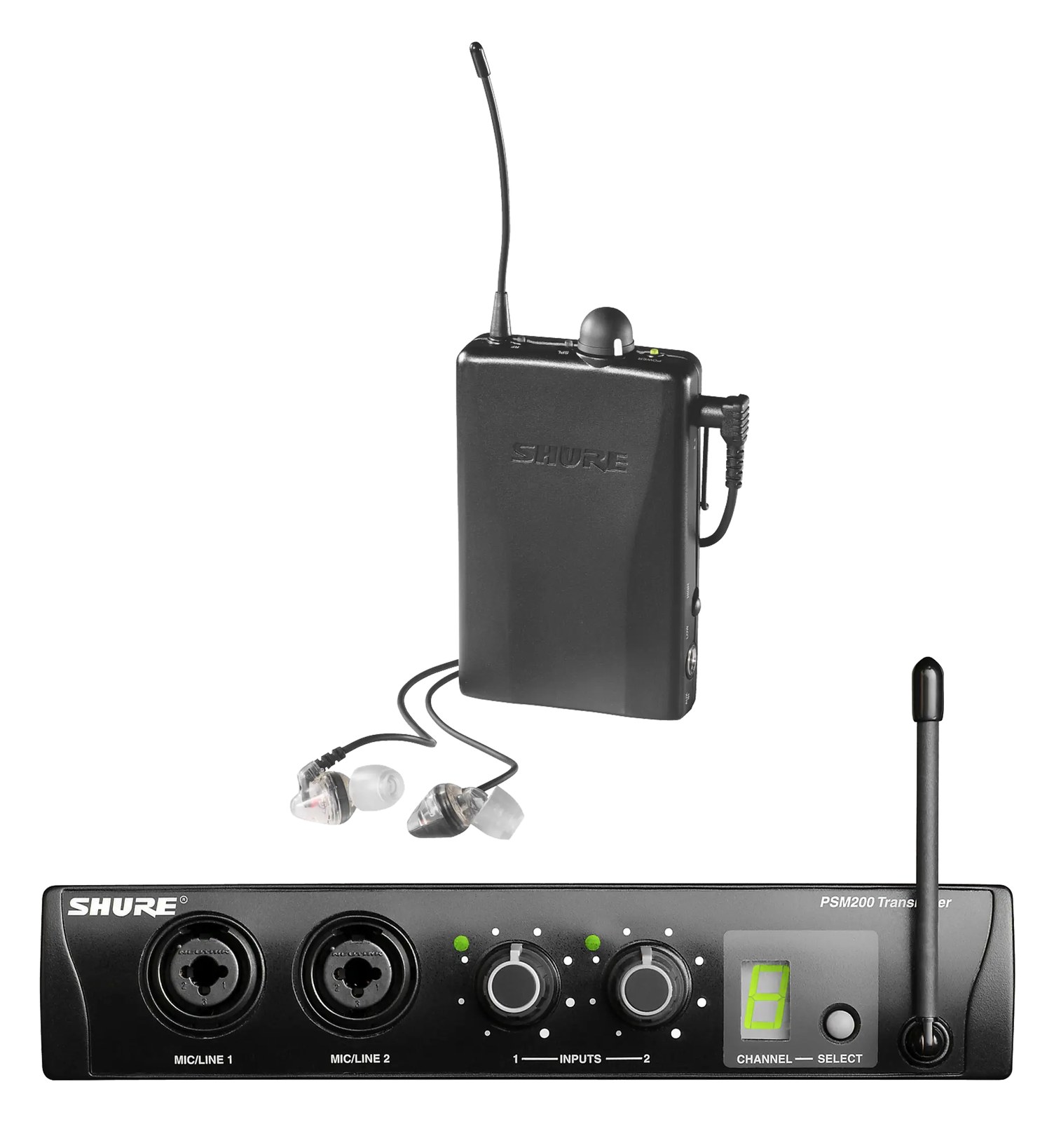
The Audio-Technica ATW-3255 puts 3000-series wireless engineering into in-ear monitoring: a half-rack transmitter with wide 138 MHz tuning, a metal bodypack receiver, and included monitor phones as a complete system under a thousand dollars. Multi-channel racks pair units two-up per row with joining plates. The credible third brand between budget and touring tiers.
~$999Use retailer rows for current price and stock
01 · What it does—and what that changes in your rig.
Product overview
Start with the payoff, then work through how it functions, where it fits, and the details that change a real build.
The payoff
IEM Transmitter decisions, organized around the whole rig.
The ATW-3255 is Audio-Technica's answer to the gap between entry-level IEMIn-Ear Monitor — earpieces that replace floor wedges, feeding each player their own mix. The reason this whole rack exists. systems that compromise on RFRadio Frequency — the wireless part of wireless. RF planning is why big rigs scan, coordinate, and combine antennas instead of hoping. performance and touring-tier gear that blows a modest budget. It ships as a complete system — half-rackThe standard slice of rack height: 1U = 1.75″. A 3U box takes three slices; half-rack gear pairs two units side by side in one. stereo transmitter, metal bodypack receiver, and monitor earphones — for under a thousand dollars. That half-rack form factor is the key detail: two units mount side by side in a single rack unit using joining plates, which keeps a multi-mix IEM rack tidy without demanding twice the vertical real estate that full-rack transmitters would.
Documented outputs
33 destination connections
Documented inputs
3Based on documented inputs
Rack space
1U · half-rackBuilder checks available rail space
Audio-Technica product panel1U · half-rack · 12W
Function
How it works in the path
The 138 MHz tuning bandwidth is the spec that matters most when you're working a venue you've never been in before. More tuning range means more room to sidestep local RFRadio Frequency — the wireless part of wireless. RF planning is why big rigs scan, coordinate, and combine antennas instead of hoping. interference, TV broadcast frequencies, or other wireless systems sharing the stage. The combo XLRThe standard 3-pin locking connector for mics and balanced line signals — pin 1 is the shield, pins 2 and 3 carry the balanced pair./TRSTip-Ring-Sleeve — a 1/4″ jack with three contacts carrying a balanced signal or a stereo pair. A guitar plug with one extra ring. inputs on both left and right channels mean you can feed it directly from an aux sendAn auxiliary mix output — each aux is its own independent blend of the channels, typically one per monitor mix or effects send. on your console without a separate DIDirect Injection box — converts an instrument’s unbalanced signal to a balanced mic-level XLR so it can run long cables without noise. or adapter in the chain. The loop outputs let you daisy-chain the audio signal to a second transmitter or a wired feed without breaking your signal path. At 12 watts typical draw, a rack of four of these pulls under 50 watts — easy to budget on a single power conditionerFilters venue AC, clamps surges, and gives the rack one tidy inlet. Not a voltage regulator and not a battery — just cleaner power. circuit.
Best fit
Where it earns its place in the rack
This system belongs in a club or theater rig where you're running two to six mixes and need a reliable, frequency-agile transmitter without paying for features a regional touring act doesn't need. It's a strong pick for a backlineThe band’s on-stage instrument gear — amps, drums, keys. What a venue or festival sometimes supplies so you can travel light. company building out a rental IEMIn-Ear Monitor — earpieces that replace floor wedges, feeding each player their own mix. The reason this whole rack exists. fleet, or a house-of-worship production team that wants quality beyond the entry tier without a capital budget fight. If you're doing stadium or arena work with dense RFRadio Frequency — the wireless part of wireless. RF planning is why big rigs scan, coordinate, and combine antennas instead of hoping. environments and 20-plus mixes, you'll want to move up to a dedicated touring platform with more granular RF scanning and coordination tools. Likewise, if your artists have strong personal earphone preferences, factor in that the included phones are a starting point rather than a destination.
In the rack
Details worth deciding before load-in.
Use joining plates to pair two ATW-3255 transmitters in one rack unitThe standard slice of rack height: 1U = 1.75″. A 3U box takes three slices; half-rack gear pairs two units side by side in one. — plan your rack in even numbers of mixes to maximize space efficiency.
Feed the loop outputs to a small passive splitter or a spare auxAn auxiliary mix output — each aux is its own independent blend of the channels, typically one per monitor mix or effects send. input on your stageboxThe I/O endpoint on stage: mics plug in there and one digital line (AES50, Dante) carries everything to the console. The snake, digitized. so FOHFront Of House — the main mix the audience hears, and the console position out in the room where it gets mixed. always has a pre-transmitter reference if you need to troubleshoot a mix without pulling cables.
Run a frequency scan before every show, not just during initial setup — the 138 MHz tuning window gives you real options if a local TV station or another act's RFRadio Frequency — the wireless part of wireless. RF planning is why big rigs scan, coordinate, and combine antennas instead of hoping. gear is encroaching on your original coordinates.
Mount the BNCThe twist-lock coax connector used for word clock and antenna runs — it locks, so it can’t be pulled out mid-show. antenna output at the back of the rack and use quality coax to run to paddlesA directional antenna (paddle, LPDA, helical) aimed at the stage — focuses coverage where the performers are and rejects RF from elsewhere. positioned with clear line of sight to the stage; the transmitter's RFRadio Frequency — the wireless part of wireless. RF planning is why big rigs scan, coordinate, and combine antennas instead of hoping. is only as good as the antenna placement you give it.
02 · Know the whole path before you buy.
Signal path
Learn the route as a block diagram: source, product function, transport, and destination. Select any block to see what enters, what changes, and what leaves.
Interactive block diagramAuto-looping · hover, focus, or tap to hold a stage
Port-type signalProduct functionSystem boundary
Follow one signal from source to destination
Each block answers the same three questions: what arrives, what changes here, and what leaves.
01 · Source · selected
XLR female + dc barrel
RJ45
bnc + ¼-inch TRS
01 · Source
3 documented inputs
XLR female + dc barrel
Arrives as
3 documented inputs
Connector
XLR female + dc barrel
Signal
analog audio
03 · What this product asks of the rest of the system.
Compatibility
Treat connector names as the start of the check—not the answer. These are the boundaries that determine a complete working path.
Best fit · IEM Transmitter
Use it when 1U · half-rack and 240 mm of depth fit the case.
Plan the companion path
Complete the path with upstream and downstream gear that matches connector, direction, signal type, protocol, and wiring standard.
Connector boundary
Documented connectors: XLR female, bnc, ¼-inch TRS, RJ45. Match connector, direction, and signal type—not shape alone.
04 · Every connector, grouped by job.
I/O ports
Switch the product view and the documented port inventory updates with it—hardware and data stay side by side.
Every connector, grouped by job.
Switch panels to keep the hardware view and the documented port list in sync.
Front panelRear panel
All documented ports for Audio-Technica ATW-3255 IEM System
Port
Panel
Connector
Direction
Signal
Channels
Input L/1 (Mono)
rear
XLR female
input
analog audio
—
Input R/2
rear
XLR female
input
analog audio
—
RF Out (Antenna)
rear
bnc
output
antenna
—
Loop Out Left
rear
¼-inch TRS
output
analog audio
—
Loop Out Right
rear
¼-inch TRS
output
analog audio
—
Network (RJ45)
rear
RJ45
bidirectional
data
—
DC In (12V)
rear
dc barrel
input
power
—
Showing 7 of 7 documented physical ports.
05 · Compare the decision, not just the price.
Alternatives
The rows are organized around fit, power, I/O, and system role so a cheaper unit cannot hide a more expensive workflow.
ATW-3255The Audio-Technica ATW-3255 puts 3000-series wireless engineering into in-ear monitoring: a half-rack transmitter with wide 138 MHz tuning, a metal bodypack receiver, and included monitor phones as a complete system under a thousand dollars. Multi-channel racks pair units two-up per row with joining plates. The credible third brand between budget and touring tiers.View gear →
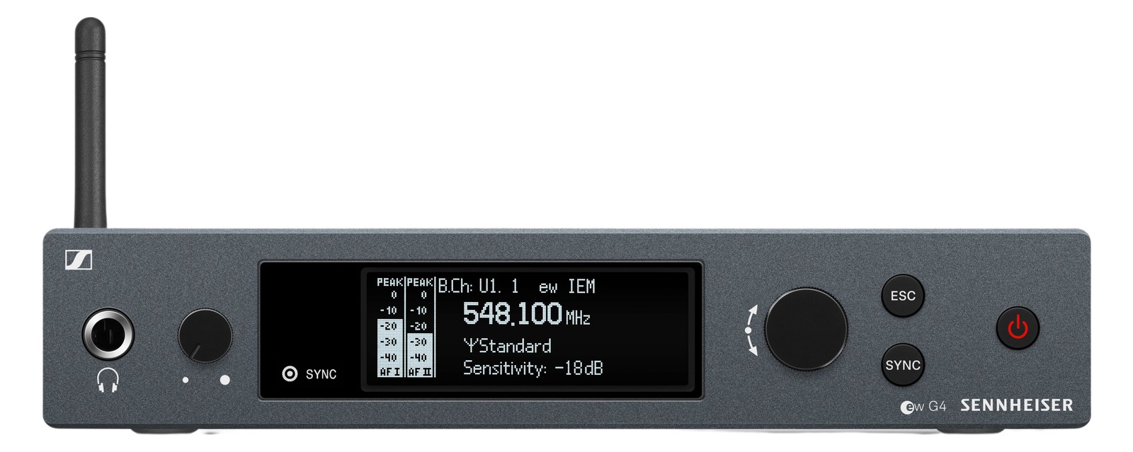
SR IEM G4Sennheiser's workhorse wireless IEM transmitter offers dependable UHF performance at a mid-range price point. The half-rack form factor keeps your rack footprint small, and the G4 platform is widely supported with a large install base. A solid alternative to Shure's PSM line for engineers already invested in the Sennheiser ecosystem or looking for a cost-effective IEM solution.View gear →
06 · Resolve the questions that can change the purchase or build plan.
Planning questions
Short, source-backed answers surface rack fit, power, cabling, and connection details before they become surprises.
How will the Audio-Technica ATW-3255 IEM System affect rack fit and case depth?
It occupies 1U · half-rack. Its documented depth is 240 mm.
How much power does the Audio-Technica ATW-3255 IEM System draw?
Typical draw is 12W and documented maximum draw is 22W.
What connections does the Audio-Technica ATW-3255 IEM System have?
7 documented physical ports, including Input L/1 (Mono), Input R/2, RF Out (Antenna), Loop Out Left, Loop Out Right, Network (RJ45).
07 · See this unit inside a real rack plan.
Builder preview
Placement is only the start. Builder checks space · depth · weight, power headroom, dependencies, and compatible signal paths around this exact catalog item.Open in Builder