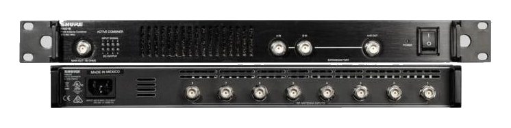
The ASA 214 is Sennheiser's entry-level antenna distribution solution, designed specifically for their Evolution Wireless and 2000 series receivers. It provides four outputs per antenna with active gain compensation, making it the right choice when you are running multiple Sennheiser wireless channels from shared antennas. If you are in the Sennheiser ecosystem, this is simpler and more cost-effective than using a third-party distro.
~$899Use retailer rows for current price and stock
01 · What it does—and what that changes in your rig.
Product overview
Start with the payoff, then work through how it functions, where it fits, and the details that change a real build.
The payoff
Antenna Distro decisions, organized around the whole rig.
The ASA 214 is a half-rackThe standard slice of rack height: 1U = 1.75″. A 3U box takes three slices; half-rack gear pairs two units side by side in one., 1U active antenna splitter that sits at the foundation of any multi-channel Sennheiser wireless rig. Its job is simple and essential: take a single pair of diversityA receiver with two antennas and two radio sections that continuously picks the stronger one — the difference between a dropout and a show. antennas and feed their signal to up to four receivers per antenna path — eight receivers total if you're running true diversity throughout. Without something like this, you're either daisy-chaining antenna outputs between receivers (lossy and messy) or running dedicated antenna cable runs to every receiver in the rack. The ASA 214 consolidates that into one tidy solution and puts your antenna placement decisions back where they belong: at the antenna, not the rack.
Documented outputs
88 destination connections
Documented inputs
3Based on documented inputs
Rack space
1U · half-rackBuilder checks available rail space
Photo: Sennheiser1U · half-rack · 5W
Function
How it works in the path
Active distribution means the unit isn't just splitting the signal passively and accepting the loss — it's compensating for it. At 5 watts nominal draw and a shallow 200mm depth, this fits without drama into a dense rack. The two independent BNCThe twist-lock coax connector used for word clock and antenna runs — it locks, so it can’t be pulled out mid-show. inputs (A and B) map cleanly to a standard dipole or paddleA directional antenna (paddle, LPDA, helical) aimed at the stage — focuses coverage where the performers are and rejects RF from elsewhere. antenna pair, and each path fans to four labeled BNC outputs, so cabling stays organized and traceable during a rushed line-checkThe quick pre-show pass confirming every input reaches the console, one line at a time. Not a soundcheck — just does it work.. The IECThe standard three-prong appliance power inlet on rack gear — the kettle lead. C13/C14 in spec-sheet speak. power connection is standard and straightforward. The key practical constraint is the four-output ceiling per path: if you're running more than eight Sennheiser receivers from a single antenna position, you'll need a second unit or a step up in the product line.
Best fit
Where it earns its place in the rack
The ASA 214 earns its place in a Sennheiser-native rack — EW G4, EW-D, EW-DX, or 2000 series — where you want a clean, manufacturer-matched solution without overbuilding. If your rig is mixed-brand wireless, a third-party distroOne pair of antennas feeding many receivers through an amplified splitter — replaces the forest of whips and keeps RF levels consistent. with wideband active amplification is likely the better call, since the ASA 214 is optimized for Sennheiser's frequency ranges and ecosystem. Similarly, if you're regularly pushing past eight channels from one antenna pair, look at Sennheiser's larger ASA series options. But for a focused Sennheiser IEMIn-Ear Monitor — earpieces that replace floor wedges, feeding each player their own mix. The reason this whole rack exists. or vocal rig in the two-to-eight-channel range, this is the right-sized, right-priced answer.
In the rack
Details worth deciding before load-in.
Mount the ASA 214 at the top of the rack, directly above your receivers — shorter BNCThe twist-lock coax connector used for word clock and antenna runs — it locks, so it can’t be pulled out mid-show. jumpers from splitter outputs to receiver inputs means less cable loss and less clutter to trace mid-show.
Label each BNCThe twist-lock coax connector used for word clock and antenna runs — it locks, so it can’t be pulled out mid-show. output (A1–A4, B1–B4) with the receiver channel it feeds before the rig leaves the shop. A label maker and five minutes now saves real confusion at a dark load-in.
Run your antenna cable to the ASA 214 inputs first, then work downstream — confirming signal at the splitter before touching receivers lets you isolate antenna placement problems from receiver problems quickly.
If you're pairing this with a half-rackThe standard slice of rack height: 1U = 1.75″. A 3U box takes three slices; half-rack gear pairs two units side by side in one. receiver like the EW-DX EM 2, two receivers can sit beside the ASA 214 in the same 1U rack space with a half-rack blank, keeping the whole system compact and in a single shallow rack.
02 · Know the whole path before you buy.
Signal path
Learn the route as a block diagram: source, product function, transport, and destination. Select any block to see what enters, what changes, and what leaves.
Interactive block diagramAuto-looping · hover, focus, or tap to hold a stage
Port-type signalProduct functionSystem boundary
Follow one signal from source to destination
Each block answers the same three questions: what arrives, what changes here, and what leaves.
01 · Source · selected
bnc + IEC C14
bnc
01 · Source
3 documented inputs
bnc + IEC C14
Arrives as
3 documented inputs
Connector
bnc + IEC C14
Signal
antenna
03 · What this product asks of the rest of the system.
Compatibility
Treat connector names as the start of the check—not the answer. These are the boundaries that determine a complete working path.
Best fit · Antenna Distro
Use it when 1U · half-rack and 200 mm of depth fit the case.
Plan the companion path
Complete the path with upstream and downstream gear that matches connector, direction, signal type, protocol, and wiring standard.
Connector boundary
Documented connectors: bnc, IEC C14. Match connector, direction, and signal type—not shape alone.
04 · Every connector, grouped by job.
I/O ports
Switch the product view and the documented port inventory updates with it—hardware and data stay side by side.
Every connector, grouped by job.
Switch panels to keep the hardware view and the documented port list in sync.
Front panelRear panel
All documented ports for Sennheiser ASA 214 Antenna Splitter
Port
Panel
Connector
Direction
Signal
Channels
Antenna In A
rear
bnc
input
antenna
—
Antenna In B
rear
bnc
input
antenna
—
Out A1
rear
bnc
output
antenna
—
Out A2
rear
bnc
output
antenna
—
Out A3
rear
bnc
output
antenna
—
Out A4
rear
bnc
output
antenna
—
Out B1
rear
bnc
output
antenna
—
Out B2
rear
bnc
output
antenna
—
Out B3
rear
bnc
output
antenna
—
Out B4
rear
bnc
output
antenna
—
Power (IEC)
rear
IEC C14
input
power
—
Showing 11 of 11 documented physical ports. Scroll to review the remaining rows.
05 · Compare the decision, not just the price.
Alternatives
The rows are organized around fit, power, I/O, and system role so a cheaper unit cannot hide a more expensive workflow.
ASA 214The ASA 214 is Sennheiser's entry-level antenna distribution solution, designed specifically for their Evolution Wireless and 2000 series receivers. It provides four outputs per antenna with active gain compensation, making it the right choice when you are running multiple Sennheiser wireless channels from shared antennas. If you are in the Sennheiser ecosystem, this is simpler and more cost-effective than using a third-party distro.View gear →
AC 41-USThe Sennheiser AC 41-US combines four IEM transmitter outputs onto one antenna, the standard move once an evolution wireless G4 monitor rack grows past two channels. Active gain stages make up the combining loss so the radiated power stays useful, and units cascade for larger systems. Half-rack chassis pairs with Sennheiser rack hardware.View gear →
ASA 1/NTThe ASA 1/NT is Sennheiser's higher-capacity antenna splitter with eight outputs per side and built-in Ethernet for remote monitoring via Sennheiser's Wireless Systems Manager software. It is purpose-built for larger Sennheiser wireless deployments where you need to monitor RF status and antenna performance from FOH or a network dashboard. The Ethernet connectivity is a significant step up from the ASA 214 for production teams that need visibility into their RF environment.View gear →
EW-D ASAThe Sennheiser EW-D ASA is the current-generation antenna splitter for Evolution Wireless Digital, feeding four EW-D or EW-DX receivers from one antenna pair and powering them over the included DC leads. It replaces the legacy ASA 1 and ASA 214 in new systems, and two units cascade for eight-channel racks. Sold as a kit with power supply and eight BNC interconnects.View gear →
06 · Resolve the questions that can change the purchase or build plan.
Planning questions
Short, source-backed answers surface rack fit, power, cabling, and connection details before they become surprises.
How will the Sennheiser ASA 214 Antenna Splitter affect rack fit and case depth?
It occupies 1U · half-rack. Its documented depth is 200 mm.
How much power does the Sennheiser ASA 214 Antenna Splitter draw?
Typical draw is 5W and documented maximum draw is 8W.
What connections does the Sennheiser ASA 214 Antenna Splitter have?
11 documented physical ports, including Antenna In A, Antenna In B, Out A1, Out A2, Out A3, Out A4.
Is the Sennheiser ASA 214 Antenna Splitter discontinued?
Superseded by EW-D ASA in current Sennheiser line; gone from major retail (Sweetwater 2026-07-21). Kept for owners.
07 · See this unit inside a real rack plan.
Builder preview
Placement is only the start. Builder checks space · depth · weight, power headroom, dependencies, and compatible signal paths around this exact catalog item.Open in Builder