
Shure UA845UWB Antenna Distro
Shure·Model UA845UWB·shure-ua845-swb
Photos
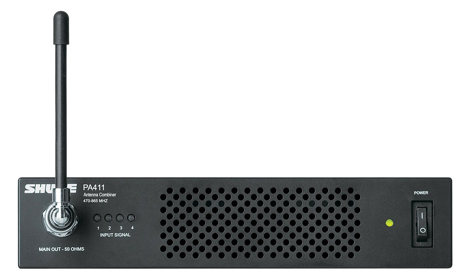
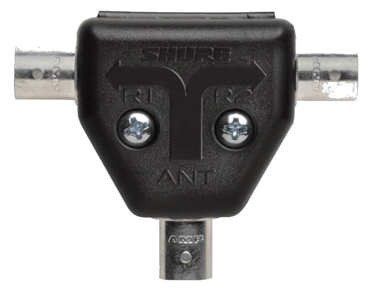
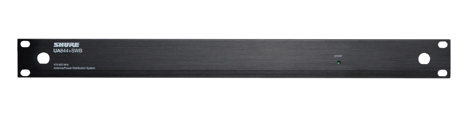
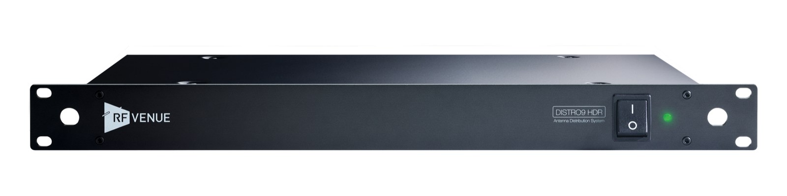
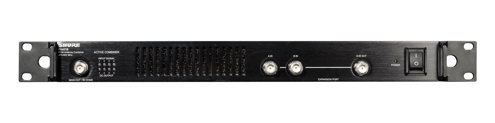
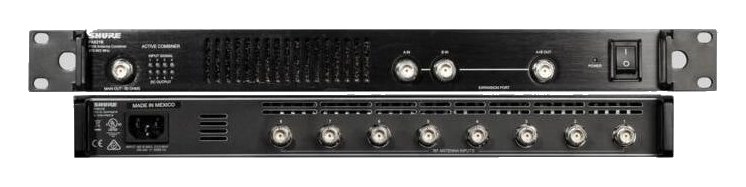
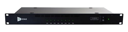
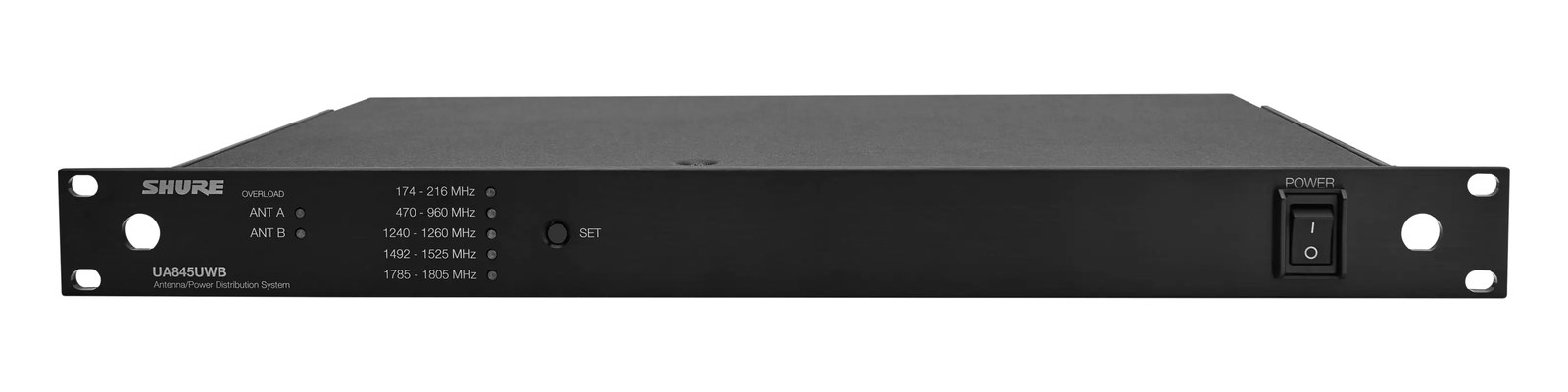
Manufacturer product photography — the drawn faceplate above stays true to panel layout; these show the hardware itself.
About the Shure UA845UWB
The UA845+SWB is the standard antenna distributionOne pair of antennas feeding many receivers through an amplified splitter — replaces the forest of whips and keeps RF levels consistent. unit for Shure PSM and ULX-D wireless systems, splitting a single antenna pair to feed up to five receivers per side. Active gainHow much the preamp amplifies the incoming signal. Too low and you’re hunting through hiss; too high and peaks clip. compensation ensures consistent signal levels across all outputs, which is critical when scaling up to larger channel counts. Essential for any rack with more than a couple of wireless receivers sharing a common antenna source.
The UA845UWB is the antenna distributionOne pair of antennas feeding many receivers through an amplified splitter — replaces the forest of whips and keeps RF levels consistent. backbone for Shure wireless rigs — specifically the piece of gear that lets you run a single pair of remote antennas and feed signal to up to five receivers per side. Without something like this, every receiver in your rack needs its own antenna run, which means cable chaos, inconsistent placement, and compounding RFRadio Frequency — the wireless part of wireless. RF planning is why big rigs scan, coordinate, and combine antennas instead of hoping. headaches as channel count climbs. Drop this in, run one clean antenna pair to the best position in the room, and every PSM or ULX-D receiver downstream sees the same signal source. That's the deal.
The 'active' part matters here. Passive splitters bleed signal every time you divide it — by the time you're feeding five receivers, you've lost meaningful headroomThe margin between your normal level and where things clip — headroom is what absorbs the snare hit you didn’t see coming.. The UA845UWB uses active gainHow much the preamp amplifies the incoming signal. Too low and you’re hunting through hiss; too high and peaks clip. compensation to keep output levels consistent across all ten outputs, so receiver number five isn't starved compared to receiver number one. At 12 watts nominal draw in a 1UThe standard slice of rack height: 1U = 1.75″. A 3U box takes three slices; half-rack gear pairs two units side by side in one. frame, it's light on rack overhead. The 230mm depth is standard for this class of unit — won't cause clearance problems in a conventional tour rack. The IECThe standard three-prong appliance power inlet on rack gear — the kettle lead. C13/C14 in spec-sheet speak. power connection means you're on your power conditionerFilters venue AC, clamps surges, and gives the rack one tidy inlet. Not a voltage regulator and not a battery — just cleaner power.'s strip, not hunting for a wall wart at load-in.
If you're running three or more Shure wireless receivers from shared antennas, this unit stops being optional and starts being the obvious answer. It's built for exactly that ecosystem — PSM 300, PSM 900, ULX-D — and the wideband design means you're not locked into a specific frequency band as your coordination needs shift. If you're running a single receiver or two, you don't need active distribution and shouldn't pay for it. If your rig is built around non-Shure wireless systems, check compatibility carefully before assuming this slots in — the outputs are standard BNCThe twist-lock coax connector used for word clock and antenna runs — it locks, so it can’t be pulled out mid-show., but system matching matters for bias voltage and impedanceOpposition to signal flow, in ohms. Low-impedance IEMs are easier to drive loud; mismatches shift level and tone..
In the rack
- Place the UA845UWB as close to the top of the rack as possible, then run your antenna cables to a single pair of paddlesA directional antenna (paddle, LPDA, helical) aimed at the stage — focuses coverage where the performers are and rejects RF from elsewhere. or helicals at the optimal position — keeping that main run short and clean is where you win or lose the RFRadio Frequency — the wireless part of wireless. RF planning is why big rigs scan, coordinate, and combine antennas instead of hoping. battle.
- Label each output port with a channel number and receiver ID before the truck leaves — ten BNCThe twist-lock coax connector used for word clock and antenna runs — it locks, so it can’t be pulled out mid-show. cables look identical under stage light and swapping them mid-show costs time you don't have.
- Budget your five outputs per side deliberately: if you have four IEMIn-Ear Monitor — earpieces that replace floor wedges, feeding each player their own mix. The reason this whole rack exists. packs and one handheld on the same antenna pair, confirm all five receivers sit within the UA845UWB's supported frequency range before load-in, not during soundcheck.
- Use a quality low-loss coax (RG8X or better) for the run from the rack to the antenna position — the active stage makes up for split loss, not for a bad cable run introducing its own attenuation upstream.
Wideband active antenna splitter/combinerThe transmit-side twin of a distro: merges several IEM transmitters into one antenna without letting them intermodulate.. 1 in, 5 out per side.
I/O Ports (18)
| Port | Connector | Direction | Signal | Channels |
|---|---|---|---|---|
| Antenna In A (BNC) | BNC | input | antenna | — |
| Antenna In B (BNC) | BNC | input | antenna | — |
| Out A1 (BNC) | BNC | output | antenna | — |
| Out A2 (BNC) | BNC | output | antenna | — |
| Out A3 (BNC) | BNC | output | antenna | — |
| Out A4 (BNC) | BNC | output | antenna | — |
| Out A5 (BNC) | BNC | output | antenna | — |
| Out B1 (BNC) | BNC | output | antenna | — |
| Out B2 (BNC) | BNC | output | antenna | — |
| Out B3 (BNC) | BNC | output | antenna | — |
| Out B4 (BNC) | BNC | output | antenna | — |
| Out B5 (BNC) | BNC | output | antenna | — |
- DC Out 1 (15V) (DC BARREL)
- DC Out 2 (15V) (DC BARREL)
- DC Out 3 (15V) (DC BARREL)
- DC Out 4 (15V) (DC BARREL)
- Power (IEC) (IEC C14)
- AC Passthrough Out (IEC) (IEC C14)
Deciding between two?
Rack space, watts, weight and every connector, side by side.
Related gear


Community rigs using this gear (3)
Browse all rigs →Related articles
Guides from our library that cover planning around antenna distro gear.
What an IEM rig actually is, the components that go into one, and how to plan your first one without overspending or blowing a circuit.
Why your wireless mics and IEMs need a frequency plan, what intermodulation means in practice, and how to coordinate channels for a clean show.
When you need a combiner vs a distro, active vs passive, cable choice and length math, and how to scale a 4-pack rig into an 8 or 12-pack without intermod nightmares.
How to build an IEM rack: choosing case size and depth, ordering gear by weight and heat, power sequencing rules, wiring practice, and a pre-show checklist.