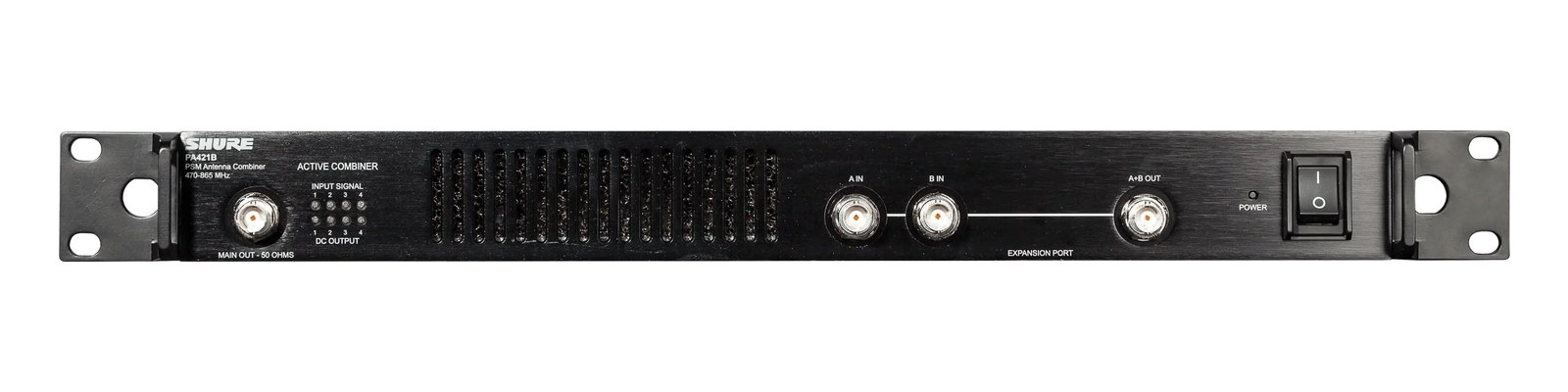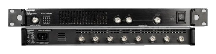

Shure UA844+SWB Antenna Distro
Shure·Model UA844+SWB·shure-ua844-swb
Photos
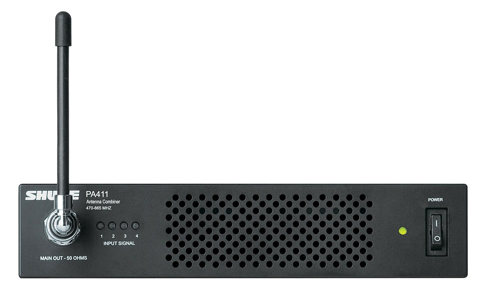
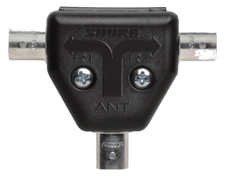
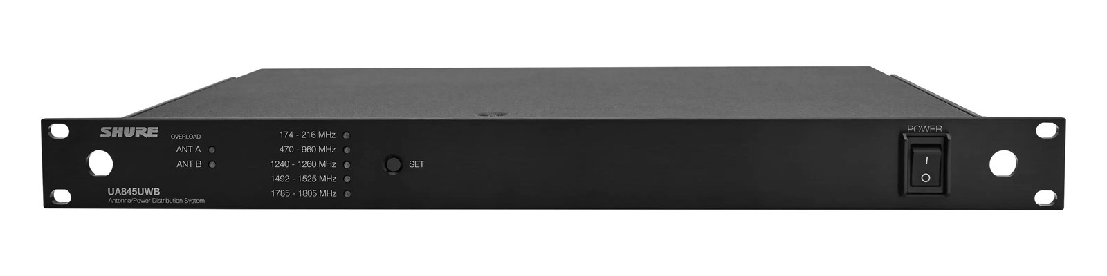
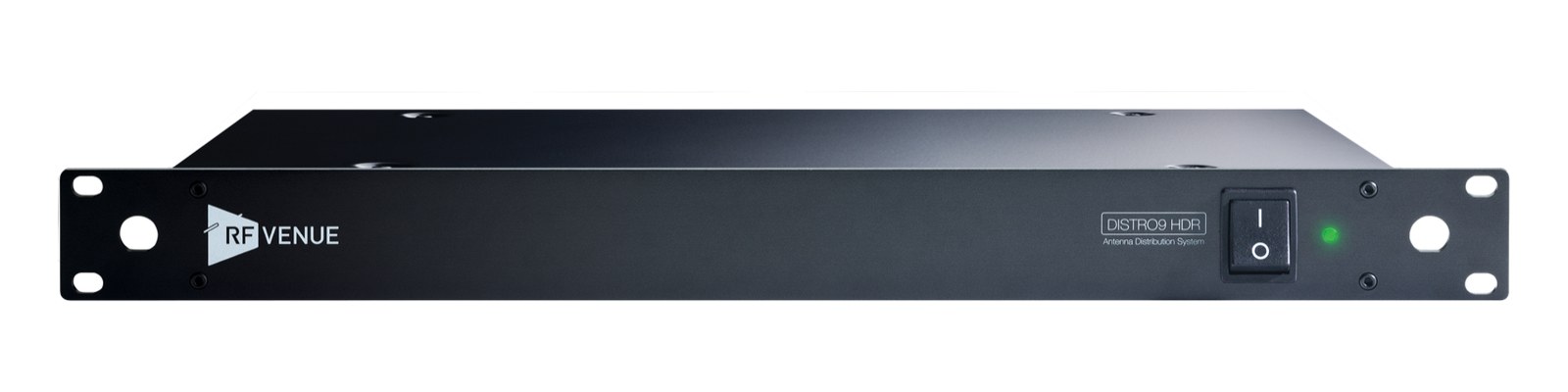
Manufacturer product photography — the drawn faceplate above stays true to panel layout; these show the hardware itself.
About the Shure UA844+SWB
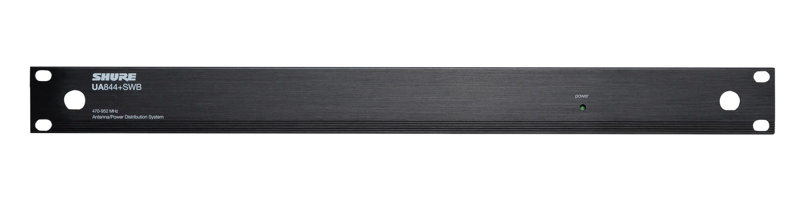
A compact and reliable antenna splitter for smaller Shure wireless deployments, the UA844+SWB distributes one antenna pair to four receivers while providing DC power to in-line antenna amplifiers. It is a great fit for rigs with up to four PSM or ULX-D receivers that need shared antenna distributionOne pair of antennas feeding many receivers through an amplified splitter — replaces the forest of whips and keeps RF levels consistent.. If you need more than four outputs, step up to the UA845+SWB.
The UA844+SWB is Shure's wideband active antenna splitter, and its job is straightforward: take one pair of antennas and feed them to up to four receivers simultaneously. In an IEMIn-Ear Monitor — earpieces that replace floor wedges, feeding each player their own mix. The reason this whole rack exists. or wireless mic rig, running a separate antenna to every receiver is a cable nightmare and a placement compromise. This unit solves that by letting you position a single A/B antenna pair optimally — on a boom at stage lip, on a stand at FOHFront Of House — the main mix the audience hears, and the console position out in the room where it gets mixed. — and then distribute that clean signal back to each receiver in the rack. At one rackspace and 1.6 kg, it fits without drama.
Ten watts of draw is negligible on any conditioned power strip. The more practically significant spec is the four-out-per-side topology: two BNCThe twist-lock coax connector used for word clock and antenna runs — it locks, so it can’t be pulled out mid-show. inputs, eight BNC outputs, all on the rear panel. The active circuitry compensates for the split loss so receivers see a healthy signal level rather than a divided one, and the unit passes DC bias to power in-line antenna amplifiers like the UA834 — meaning you don't need a separate power run to a remote amp when you're pushing antennas a long cable run away. At 230 mm deep it's a standard shallow-rack depth, so it won't fight you in a tight tour pack.
If your rig runs four or fewer Shure wireless channels — PSM300, PSM900, ULX-D, or similar — this is the natural, well-proven choice. It's designed around Shure's own ecosystem, so compatibility is a non-issue. Where it stops making sense is when you cross the four-receiver threshold: the catalog record itself points to the UA845+SWB for larger deployments, and trying to daisy-chain two UA844s introduces complexity that the larger unit handles cleanly. It also won't do you much good if your receivers are non-Shure and require a different impedanceOpposition to signal flow, in ohms. Low-impedance IEMs are easier to drive loud; mismatches shift level and tone. or connector standard — verify compatibility before committing.
In the rack
- Run your antenna cables to the inputs first and confirm signal presence on each receiver before patching audio — a bad BNCThe twist-lock coax connector used for word clock and antenna runs — it locks, so it can’t be pulled out mid-show. at the distroOne pair of antennas feeding many receivers through an amplified splitter — replaces the forest of whips and keeps RF levels consistent. input kills all four channels at once, so catching it early saves the soundcheck.
- When using a remote in-line amp like the UA834, route DC bias through this unit's BNCThe twist-lock coax connector used for word clock and antenna runs — it locks, so it can’t be pulled out mid-show. outputs rather than adding a separate power supply; the UA844+SWB is designed to carry that bias down the coax, keeping your cable count down.
- Place this unit directly above or below your receivers in the rack so BNCThe twist-lock coax connector used for word clock and antenna runs — it locks, so it can’t be pulled out mid-show. patch cables from the outputs stay short and tidy — long BNC runs between the distroOne pair of antennas feeding many receivers through an amplified splitter — replaces the forest of whips and keeps RF levels consistent. and receivers inside the rack are unnecessary and add connectors that can work loose on the road.
- Label the A-side and B-side output ports with the receiver slot they feed before the rig ships; swapped antenna connections are a silent problem that only shows up as range dropoutsA brief audio gap when the radio link fails — the thing diversity, distros, and coordination all exist to prevent. mid-show.
Wideband active antenna splitter. 1 in, 4 out per side (A/B). Powers in-line amplifiers.
I/O Ports (11)
| Port | Connector | Direction | Signal | Channels |
|---|---|---|---|---|
| Antenna In A | BNC | input | antenna | — |
| Antenna In B | BNC | input | antenna | — |
| Out A1 | BNC | output | antenna | — |
| Out A2 | BNC | output | antenna | — |
| Out A3 | BNC | output | antenna | — |
| Out A4 | BNC | output | antenna | — |
| Out B1 | BNC | output | antenna | — |
| Out B2 | BNC | output | antenna | — |
| Out B3 | BNC | output | antenna | — |
| Out B4 | BNC | output | antenna | — |
- Power (IEC) (IEC C14)
Deciding between two?
Rack space, watts, weight and every connector, side by side.
Related gear


Related articles
Guides from our library that cover planning around antenna distro gear.
What an IEM rig actually is, the components that go into one, and how to plan your first one without overspending or blowing a circuit.
Why your wireless mics and IEMs need a frequency plan, what intermodulation means in practice, and how to coordinate channels for a clean show.
When you need a combiner vs a distro, active vs passive, cable choice and length math, and how to scale a 4-pack rig into an 8 or 12-pack without intermod nightmares.
How to build an IEM rack: choosing case size and depth, ordering gear by weight and heat, power sequencing rules, wiring practice, and a pre-show checklist.