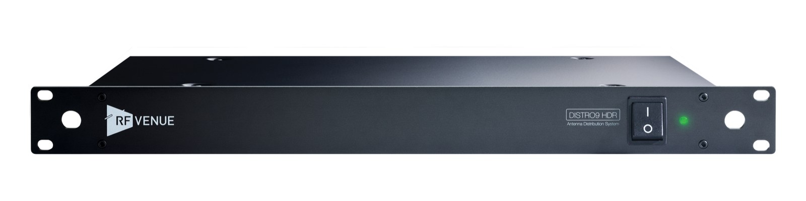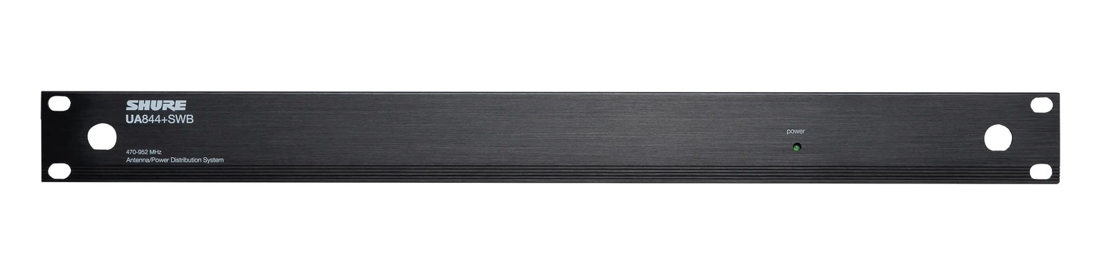

Shure PA421B Antenna Combiner
Shure·Model PA421B·shure-pa421a
Photos
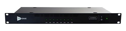
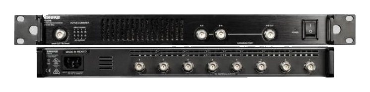
Manufacturer product photography — the drawn faceplate above stays true to panel layout; these show the hardware itself.
About the Shure PA421B
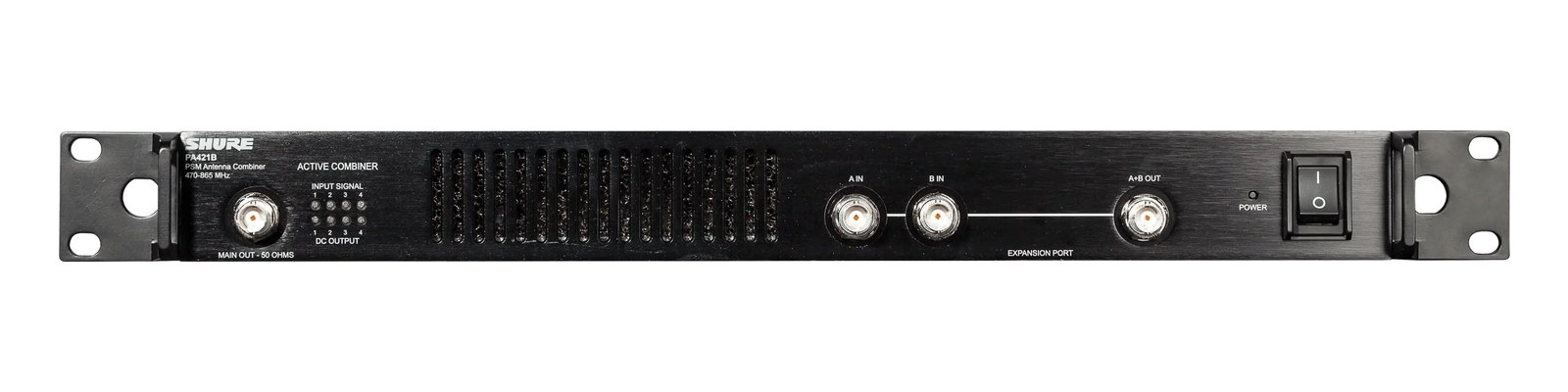
The PA421B lets you combine up to four IEMIn-Ear Monitor — earpieces that replace floor wedges, feeding each player their own mix. The reason this whole rack exists. transmitter RFRadio Frequency — the wireless part of wireless. RF planning is why big rigs scan, coordinate, and combine antennas instead of hoping. outputs into a single antenna, dramatically reducing the number of antennas needed on stage. This is essential for clean deployments where multiple PSM transmitters share a common antenna rather than each having its own. The active gainHow much the preamp amplifies the incoming signal. Too low and you’re hunting through hiss; too high and peaks clip. stage makes up the combining loss, and four 15 V DC outputs on the rear can power the transmitters feeding it.
The PA421B is a passive 4-to-1 RFRadio Frequency — the wireless part of wireless. RF planning is why big rigs scan, coordinate, and combine antennas instead of hoping. combinerThe transmit-side twin of a distro: merges several IEM transmitters into one antenna without letting them intermodulate. designed to consolidate the antenna outputs of up to four PSM-series IEMIn-Ear Monitor — earpieces that replace floor wedges, feeding each player their own mix. The reason this whole rack exists. transmitters into a single broadband antenna. Instead of running four antennas off four transmitters and turning your stage wings into a forest of paddlesA directional antenna (paddle, LPDA, helical) aimed at the stage — focuses coverage where the performers are and rejects RF from elsewhere., you feed each transmitter's RF output into one of the four BNCThe twist-lock coax connector used for word clock and antenna runs — it locks, so it can’t be pulled out mid-show. inputs and drive a single antenna from the combined output. That single antenna still covers all four transmitter channels simultaneously. For anyone running a multi-pack PSM system, this is how a tidy, professional deployment actually happens.
Passive design is the headline spec that matters most here. The PA421B draws zero watts — nothing to power, nothing to configure, nothing to fail mid-show in the way an active component could. The tradeoff is insertion loss: combining four RFRadio Frequency — the wireless part of wireless. RF planning is why big rigs scan, coordinate, and combine antennas instead of hoping. signals passively means each transmitter sees some loss before the signal reaches the antenna, so you'll want to verify your link budget still has enough headroomThe margin between your normal level and where things clip — headroom is what absorbs the snare hit you didn’t see coming. for your venue size. At 1UThe standard slice of rack height: 1U = 1.75″. A 3U box takes three slices; half-rack gear pairs two units side by side in one. and 200mm deep, it sits cleanly in a standard IEMIn-Ear Monitor — earpieces that replace floor wedges, feeding each player their own mix. The reason this whole rack exists. rack without reaching back into the bay. At 1.4 kg it's light enough that it won't stress a shelf mount, though you should still rack it properly.
If you're running two, three, or four PSM300 or PSM900 packs and want a clean antenna solution without a powered distroOne pair of antennas feeding many receivers through an amplified splitter — replaces the forest of whips and keeps RF levels consistent., this is a direct, reliable answer. It's also the right call when your system tech wants to minimize active components in the RFRadio Frequency — the wireless part of wireless. RF planning is why big rigs scan, coordinate, and combine antennas instead of hoping. chain. Where it's not the right fit: if you need to feed a remote active antenna distro like a Shure AD4D setup, or if you're combining antennas on the receive side for wireless mics rather than transmitters — this is transmitter-side only. Larger touring systems with more than four packs will need multiple units or a different architecture entirely.
In the rack
- Verify transmitter output power settings after patching through the combinerThe transmit-side twin of a distro: merges several IEM transmitters into one antenna without letting them intermodulate. — some engineers drop PSM transmitter output to its lowest effective setting to minimize intermodulationIntermodulation — ghost frequencies created when transmitters mix in each other’s electronics. Why multi-channel wireless is calculated, not guessed. between combined channels.
- Run the combined output to your antenna with the shortest quality coax run you can manage; passive combinersThe transmit-side twin of a distro: merges several IEM transmitters into one antenna without letting them intermodulate. can't make up for cable loss downstream the way an active amp can.
- Label each BNCThe twist-lock coax connector used for word clock and antenna runs — it locks, so it can’t be pulled out mid-show. input with the pack number and frequency at patch — during a fast changeover in a dark wing, unlabeled BNC inputs on a black faceplate all look identical.
- If you're stacking two PA421B units to cover eight transmitters, use a second passive combinerThe transmit-side twin of a distro: merges several IEM transmitters into one antenna without letting them intermodulate. or a quality splitter to feed both combined outputs to one antenna, and re-check your link margin — you're now two stages of passive loss deep.
4-to-1 ACTIVE antenna combinerThe transmit-side twin of a distro: merges several IEM transmitters into one antenna without letting them intermodulate. for PSM transmitters. IECThe standard three-prong appliance power inlet on rack gear — the kettle lead. C13/C14 in spec-sheet speak. mains in; four 15V DC outputs power the transmitters. Front silkscreen reads "ACTIVE COMBINER".
I/O Ports (13)
| Port | Connector | Direction | Signal | Channels |
|---|---|---|---|---|
| Input 1 | BNC | input | antenna | — |
| Input 2 | BNC | input | antenna | — |
| Input 3 | BNC | input | antenna | — |
| Input 4 | BNC | input | antenna | — |
| Main Out (50Ω, front) | BNC | output | antenna | — |
| Expansion A In (front) | BNC | input | antenna | — |
| Expansion B In (front) | BNC | input | antenna | — |
| Expansion A+B Out (front) | BNC | output | antenna | — |
- DC Out 1 (15V) (DC BARREL)
- DC Out 2 (15V) (DC BARREL)
- DC Out 3 (15V) (DC BARREL)
- DC Out 4 (15V) (DC BARREL)
- Power (IEC) (IEC C14)
Deciding between two?
Rack space, watts, weight and every connector, side by side.
Related gear


Related articles
Guides from our library that cover planning around antenna distro gear.
What an IEM rig actually is, the components that go into one, and how to plan your first one without overspending or blowing a circuit.
Why your wireless mics and IEMs need a frequency plan, what intermodulation means in practice, and how to coordinate channels for a clean show.
When you need a combiner vs a distro, active vs passive, cable choice and length math, and how to scale a 4-pack rig into an 8 or 12-pack without intermod nightmares.
How to build an IEM rack: choosing case size and depth, ordering gear by weight and heat, power sequencing rules, wiring practice, and a pre-show checklist.