
Shure PA821B Antenna Combiner
Shure·Model PA821B·shure-pa821a
Photos
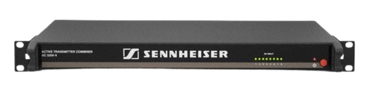
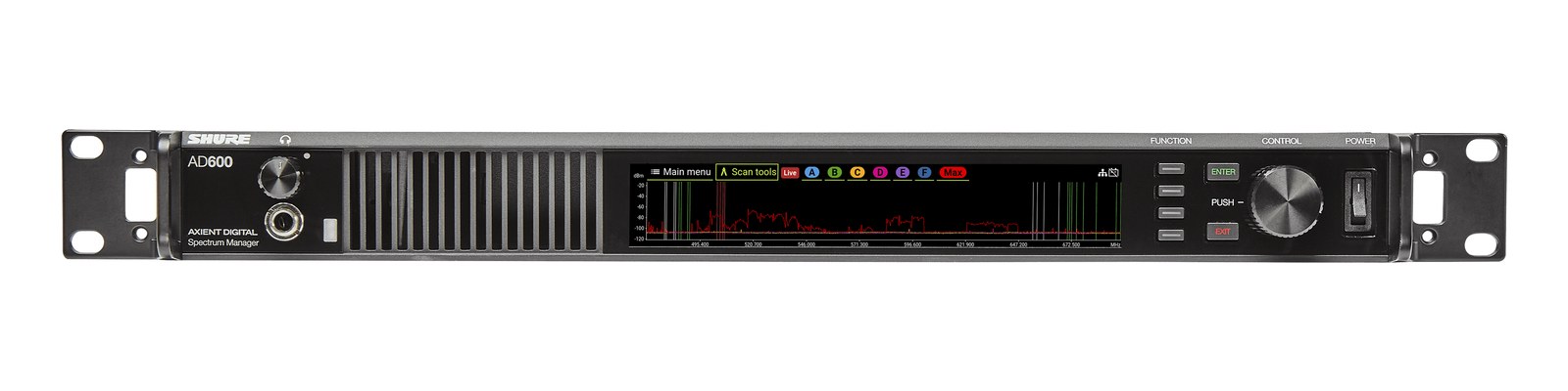
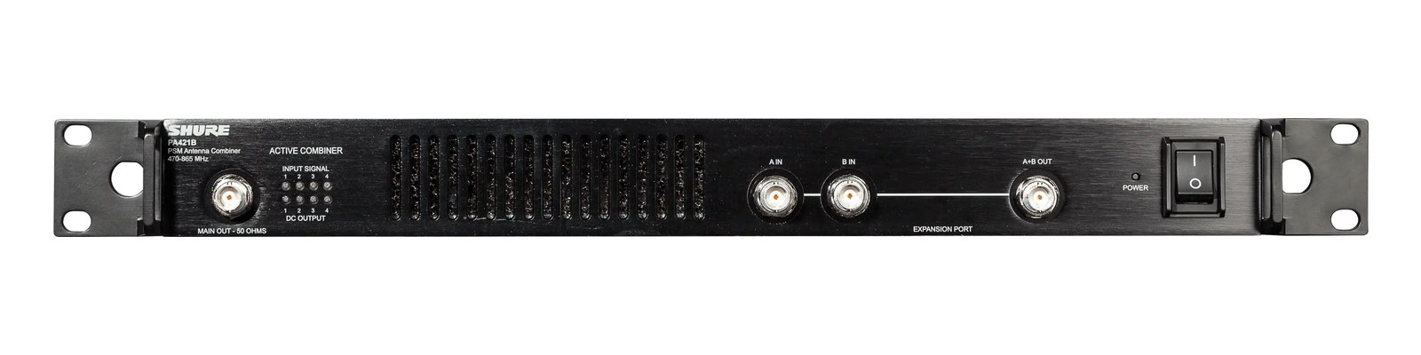
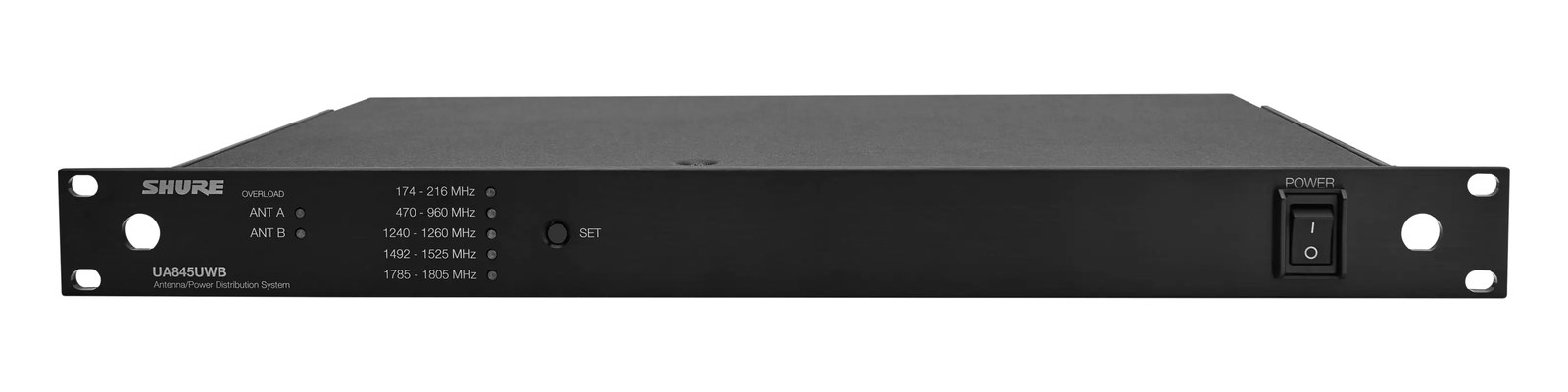
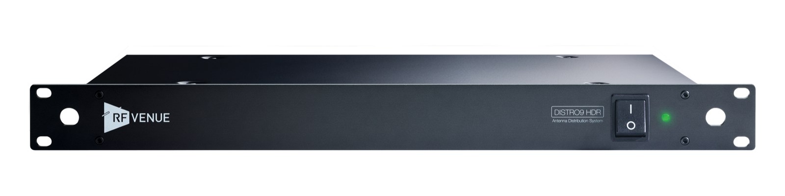
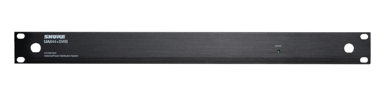
Manufacturer product photography — the drawn faceplate above stays true to panel layout; these show the hardware itself.
About the Shure PA821B
The PA821A is the larger sibling of the PA421A, combining eight IEMIn-Ear Monitor — earpieces that replace floor wedges, feeding each player their own mix. The reason this whole rack exists. transmitter outputs into a single antenna pair with active filtering to maintain signal integrity. Built-in bandpass filters help keep your transmitted signals clean and reduce intermodIntermodulation — ghost frequencies created when transmitters mix in each other’s electronics. Why multi-channel wireless is calculated, not guessed. products, which matters in crowded RFRadio Frequency — the wireless part of wireless. RF planning is why big rigs scan, coordinate, and combine antennas instead of hoping. environments. This is a touring-grade solution for rigs running six or more IEM channels from a single rack.
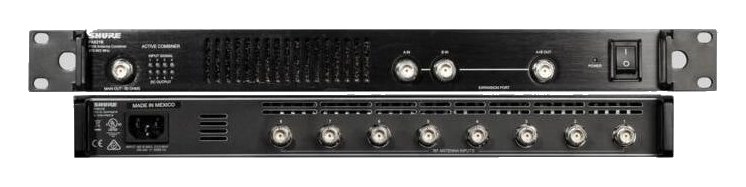
The PA821B is an 8-input active antenna combinerThe transmit-side twin of a distro: merges several IEM transmitters into one antenna without letting them intermodulate. designed to consolidate the RFRadio Frequency — the wireless part of wireless. RF planning is why big rigs scan, coordinate, and combine antennas instead of hoping. outputs of up to eight IEMIn-Ear Monitor — earpieces that replace floor wedges, feeding each player their own mix. The reason this whole rack exists. transmitters into a single antenna pair. Instead of running individual whip antennasThe stock quarter-wave stick antenna that screws straight onto a receiver — fine for a channel or two in a small room. off every transmitter in the rack, you feed all eight transmitter outputs into this unit and hang one set of antennas — paddlesA directional antenna (paddle, LPDA, helical) aimed at the stage — focuses coverage where the performers are and rejects RF from elsewhere., sharks, whatever your preference — from the two combined outputs. That single antenna run then covers your entire IEM rig, which is the only sane approach once you're past four or five channels and stage real estate for antennas starts to become its own logistical problem.
At 1UThe standard slice of rack height: 1U = 1.75″. A 3U box takes three slices; half-rack gear pairs two units side by side in one. and 230mm deep, it parks cleanly in a standard tour rack without eating much space. The 12-watt draw is negligible. What actually matters at show time is what the active filtering is doing inside: the built-in bandpass filters are working to suppress intermodulationIntermodulation — ghost frequencies created when transmitters mix in each other’s electronics. Why multi-channel wireless is calculated, not guessed. products that would otherwise develop when you're summing multiple transmitter signals together. In a crowded RFRadio Frequency — the wireless part of wireless. RF planning is why big rigs scan, coordinate, and combine antennas instead of hoping. environment — festival stages, arenas with house systems sharing the same spectrum — that filtering is the difference between a clean combine and a rack that's generating its own interference. The two combined outputs give you a redundantA second copy of anything critical — supply, computer, network path — already running so one failure can’t stop the show. antenna path, which matters when a cable gets kicked.
This unit is purpose-built for rigs running six to eight PSM or similar IEMIn-Ear Monitor — earpieces that replace floor wedges, feeding each player their own mix. The reason this whole rack exists. transmitters that need a single, managed antenna deployment. If you're running four channels or fewer, the PA421A is the more proportionate tool and costs considerably less. If you're mixing transmitter brands and aren't certain of compatibility with Shure's combining architecture, verify before committing — active combinersThe transmit-side twin of a distro: merges several IEM transmitters into one antenna without letting them intermodulate. like this are optimized for the impedanceOpposition to signal flow, in ohms. Low-impedance IEMs are easier to drive loud; mismatches shift level and tone. and power characteristics of the transmitters they're paired with. Rental houses running large Shure IEM inventories will find this indispensable; a smaller regional rig with two transmitters will find it overkill.
In the rack
- Route the two combined outputs to your antenna pair as A and B diversityA receiver with two antennas and two radio sections that continuously picks the stronger one — the difference between a dropout and a show. inputs — don't leave one output unused, as the redundancyA second copy of anything critical — supply, computer, network path — already running so one failure can’t stop the show. is the point of having two.
- Keep BNCThe twist-lock coax connector used for word clock and antenna runs — it locks, so it can’t be pulled out mid-show. cable runs from each transmitter to the PA821B as short and equal in length as practical; uneven cable losses across the eight inputs can affect how well the filtering performs.
- Mount it immediately adjacent to your transmitter stack in the rack so transmitter-to-combinerThe transmit-side twin of a distro: merges several IEM transmitters into one antenna without letting them intermodulate. BNCThe twist-lock coax connector used for word clock and antenna runs — it locks, so it can’t be pulled out mid-show. jumpers stay short and tidy — long exposed BNC runs between transmitters and the combiner are an unnecessary failure point at load-in.
- Label each BNCThe twist-lock coax connector used for word clock and antenna runs — it locks, so it can’t be pulled out mid-show. input on the unit's face with the channel it corresponds to before the show; when a transmitter needs to be swapped mid-day, you don't want to be tracing cables under stage lighting.
8-to-1 active antenna combinerThe transmit-side twin of a distro: merges several IEM transmitters into one antenna without letting them intermodulate.. Combines 8 PSM/IEMIn-Ear Monitor — earpieces that replace floor wedges, feeding each player their own mix. The reason this whole rack exists. transmitter outputs into a single antenna pair with filtering.
I/O Ports (13)
| Port | Connector | Direction | Signal | Channels |
|---|---|---|---|---|
| Input 1 | BNC | input | antenna | — |
| Input 2 | BNC | input | antenna | — |
| Input 3 | BNC | input | antenna | — |
| Input 4 | BNC | input | antenna | — |
| Input 5 | BNC | input | antenna | — |
| Input 6 | BNC | input | antenna | — |
| Input 7 | BNC | input | antenna | — |
| Input 8 | BNC | input | antenna | — |
| Main Out (50Ω, front) | BNC | output | antenna | — |
| Expansion A+B Out (front) | BNC | output | antenna | — |
| Expansion A In (front) | BNC | input | antenna | — |
| Expansion B In (front) | BNC | input | antenna | — |
- Power (IEC) (IEC C14)
Deciding between two?
Rack space, watts, weight and every connector, side by side.
Related gear


Related articles
Guides from our library that cover planning around antenna distro gear.
What an IEM rig actually is, the components that go into one, and how to plan your first one without overspending or blowing a circuit.
Why your wireless mics and IEMs need a frequency plan, what intermodulation means in practice, and how to coordinate channels for a clean show.
When you need a combiner vs a distro, active vs passive, cable choice and length math, and how to scale a 4-pack rig into an 8 or 12-pack without intermod nightmares.
How to build an IEM rack: choosing case size and depth, ordering gear by weight and heat, power sequencing rules, wiring practice, and a pre-show checklist.