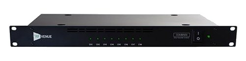
RF Venue's COMBINE4 is a brand-agnostic passive antenna combiner that merges four transmitter outputs into one antenna feed. Its half-rack form factor saves valuable rack space, and the passive design keeps things simple with no power requirements. A solid choice for smaller IEM rigs where you want to reduce antenna clutter on stage without investing in a full active combiner.
UnverifiedPower requirement is not verified in the catalog
Catalog estimate
~$849Use retailer rows for current price and stock
01 · What it does—and what that changes in your rig.
Product overview
Start with the payoff, then work through how it functions, where it fits, and the details that change a real build.
The payoff
Antenna Distro decisions, organized around the whole rig.
The COMBINE4 handles the transmit-side antenna problem for IEMIn-Ear Monitor — earpieces that replace floor wedges, feeding each player their own mix. The reason this whole rack exists. racks: four transmitters, each wanting to radiate, in a rack where four whip antennasThe stock quarter-wave stick antenna that screws straight onto a receiver — fine for a channel or two in a small room. would intermodulate into a mess of phantomThe +48 V a console sends up the mic cable to power condenser mics and active DI boxes — invisible to gear that doesn’t need it. carriers. It passively combines the four RFRadio Frequency — the wireless part of wireless. RF planning is why big rigs scan, coordinate, and combine antennas instead of hoping. outputs into one feed for a single transmit antenna — no power supply, no active gainHow much the preamp amplifies the incoming signal. Too low and you’re hunting through hiss; too high and peaks clip. stage to fail mid-show, just careful passive combining with the isolation between ports doing the real work of keeping transmitters out of each other's output stages.
Documented outputs
1One destination connection
Documented inputs
5Based on documented inputs
Rack space
1UBuilder checks available rail space
Photo: RF Venue1U · Unverified
Function
How it works in the path
Passive is the load-bearing word: with no amplifier making up the combining loss, the unit trades a few dB of output for total reliability and zero added intermodIntermodulation — ghost frequencies created when transmitters mix in each other’s electronics. Why multi-channel wireless is calculated, not guessed. — the correct trade for IEMIn-Ear Monitor — earpieces that replace floor wedges, feeding each player their own mix. The reason this whole rack exists. transmit, where receivers are human-worn and close. Being brand-agnostic, it doesn't care whether the four inputs are Shure, Sennheiser, or a mixed rack, which is exactly the real world of rental inventory.
Best fit
Where it earns its place in the rack
It pairs naturally with a helicalA directional antenna (paddle, LPDA, helical) aimed at the stage — focuses coverage where the performers are and rejects RF from elsewhere. or LPDA transmit antenna remoted above the stage clutter, and its half-rackThe standard slice of rack height: 1U = 1.75″. A 3U box takes three slices; half-rack gear pairs two units side by side in one. width means the standard RFRadio Frequency — the wireless part of wireless. RF planning is why big rigs scan, coordinate, and combine antennas instead of hoping. row is this plus a DISTRO4 side by side in 1U: transmit combining on one side, receive distribution on the other, one antenna run each way.
In the rack
Details worth deciding before load-in.
Send the combined output to one remoted helicalA directional antenna (paddle, LPDA, helical) aimed at the stage — focuses coverage where the performers are and rejects RF from elsewhere./paddle — height and sightline to the performers matter more than gainHow much the preamp amplifies the incoming signal. Too low and you’re hunting through hiss; too high and peaks clip..
Passive loss is by design; set transmitter power accordingly rather than reaching for an amplified combinerThe transmit-side twin of a distro: merges several IEM transmitters into one antenna without letting them intermodulate..
Mount beside a DISTRO4 in one 1UThe standard slice of rack height: 1U = 1.75″. A 3U box takes three slices; half-rack gear pairs two units side by side in one. row for the classic transmit-plus-receive RFRadio Frequency — the wireless part of wireless. RF planning is why big rigs scan, coordinate, and combine antennas instead of hoping. shelf.
02 · Know the whole path before you buy.
Signal path
Learn the route as a block diagram: source, product function, transport, and destination. Select any block to see what enters, what changes, and what leaves.
Interactive block diagramAuto-looping · hover, focus, or tap to hold a stage
Port-type signalProduct functionSystem boundary
Follow one signal from source to destination
Each block answers the same three questions: what arrives, what changes here, and what leaves.
01 · Source · selected
bnc + IEC C14
bnc
01 · Source
5 documented inputs
bnc + IEC C14
Arrives as
5 documented inputs
Connector
bnc + IEC C14
Signal
antenna
03 · What this product asks of the rest of the system.
Compatibility
Treat connector names as the start of the check—not the answer. These are the boundaries that determine a complete working path.
Best fit · Antenna Distro
Use it when 1U and 250 mm of depth fit the case.
Plan the companion path
Complete the path with upstream and downstream gear that matches connector, direction, signal type, protocol, and wiring standard.
Connector boundary
Documented connectors: bnc, IEC C14, dc barrel. Match connector, direction, and signal type—not shape alone.
04 · Every connector, grouped by job.
I/O ports
Switch the product view and the documented port inventory updates with it—hardware and data stay side by side.
Every connector, grouped by job.
Switch panels to keep the hardware view and the documented port list in sync.
Front panelRear panel
All documented ports for RF Venue COMBINE4 Antenna Combiner
Port
Panel
Connector
Direction
Signal
Channels
RF IN 1
rear
bnc
input
antenna
—
RF IN 2
rear
bnc
input
antenna
—
RF IN 3
rear
bnc
input
antenna
—
RF IN 4
rear
bnc
input
antenna
—
ANTENNA OUTPUT
rear
bnc
output
antenna
—
AC POWER
rear
IEC C14
input
power
—
DC OUT 1
rear
dc barrel
bidirectional
power
—
DC OUT 2
rear
dc barrel
bidirectional
power
—
DC OUT 3
rear
dc barrel
bidirectional
power
—
DC OUT 4
rear
dc barrel
bidirectional
power
—
Showing 10 of 10 documented physical ports.
05 · Compare the decision, not just the price.
Alternatives
The rows are organized around fit, power, I/O, and system role so a cheaper unit cannot hide a more expensive workflow.
COMBINE4RF Venue's COMBINE4 is a brand-agnostic passive antenna combiner that merges four transmitter outputs into one antenna feed. Its half-rack form factor saves valuable rack space, and the passive design keeps things simple with no power requirements. A solid choice for smaller IEM rigs where you want to reduce antenna clutter on stage without investing in a full active combiner.View gear →
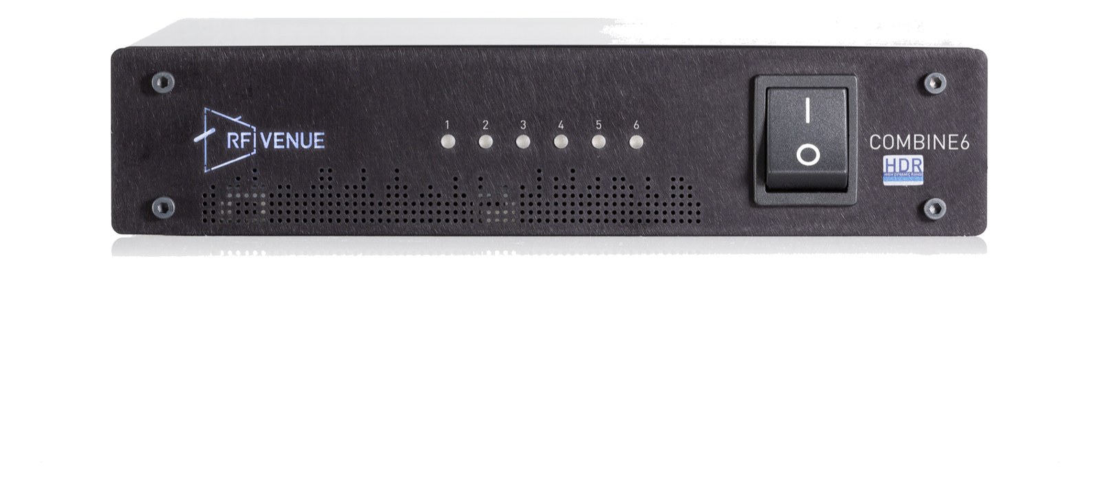
COMBINE6 HDRThe RF Venue COMBINE6 HDR squeezes a six-input IEM transmitter combiner into half a rack space, with high dynamic range RF stages built for the crowded UHF landscape. Passive RF in/out expansion ports chain a second unit for larger monitor rigs, and the single antenna output feeds a CP Beam or helical for clean transmit coverage. A dense, current-generation alternative to the classic 4:1 combiners.View gear →
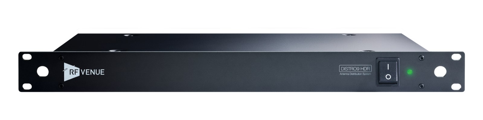
DISTRO4The RF Venue DISTRO4 is a full-width 1U antenna distribution system with four diversity receiver feeds plus cascade outputs. It provides active gain to compensate for splitting losses and an internal supply for receiver power, keeping a multi-channel wireless rack consolidated in one chassis.View gear →
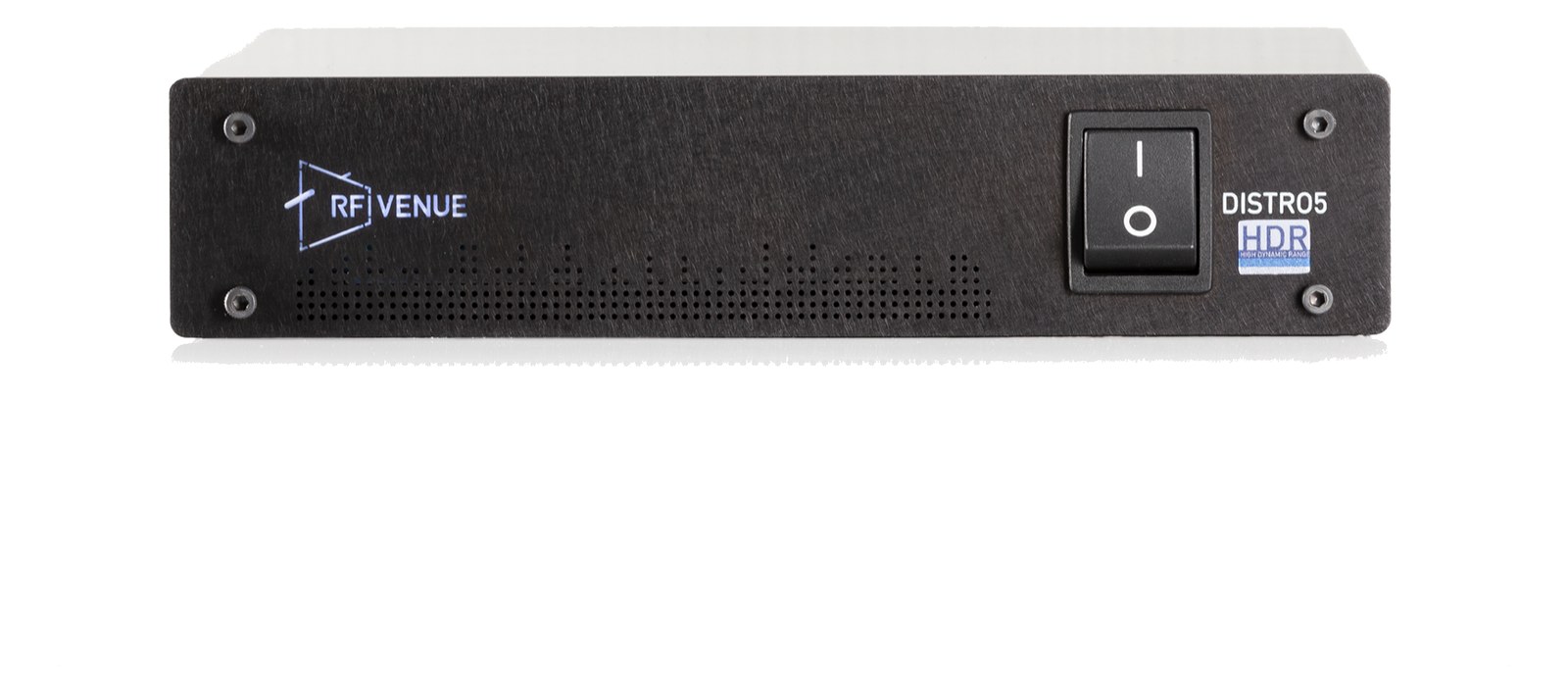
DISTRO5 HDRThe RF Venue DISTRO5 HDR feeds five diversity receiver pairs from one antenna pair in half a rack space, with DC power distribution for the receivers and the ability to run on battery power for remote or portable rigs. High dynamic range amplification keeps strong local transmitters from swamping the mic receivers downstream. Cascade ports extend the system when channel counts grow.View gear →
06 · Resolve the questions that can change the purchase or build plan.
Planning questions
Short, source-backed answers surface rack fit, power, cabling, and connection details before they become surprises.
How will the RF Venue COMBINE4 Antenna Combiner affect rack fit and case depth?
It occupies 1U. Its documented depth is 250 mm.
How much power does the RF Venue COMBINE4 Antenna Combiner draw?
Its power requirement is not yet verified in the catalog.
What connections does the RF Venue COMBINE4 Antenna Combiner have?
10 documented physical ports, including RF IN 1, RF IN 2, RF IN 3, RF IN 4, ANTENNA OUTPUT, AC POWER.
07 · See this unit inside a real rack plan.
Builder preview
Placement is only the start. Builder checks space · depth · weight, power headroom, dependencies, and compatible signal paths around this exact catalog item.Open in Builder