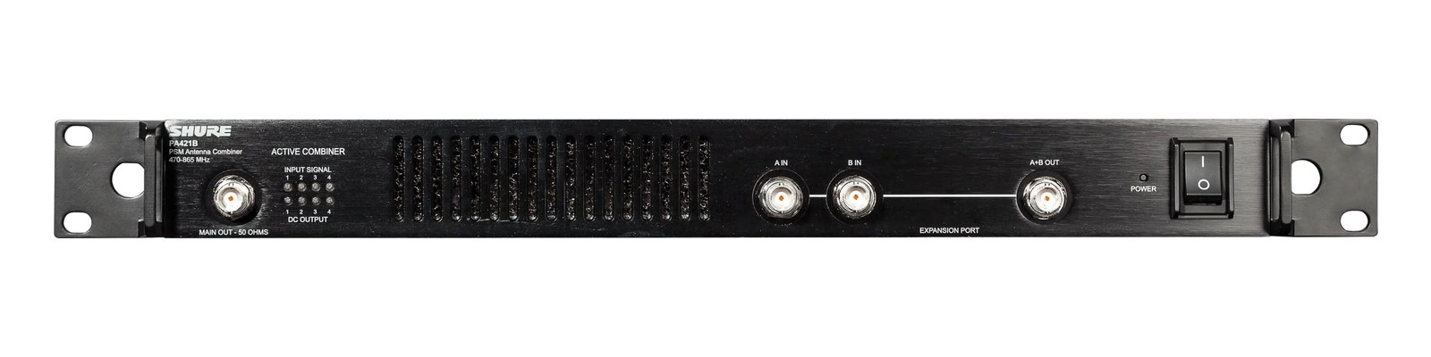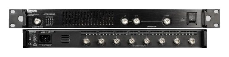

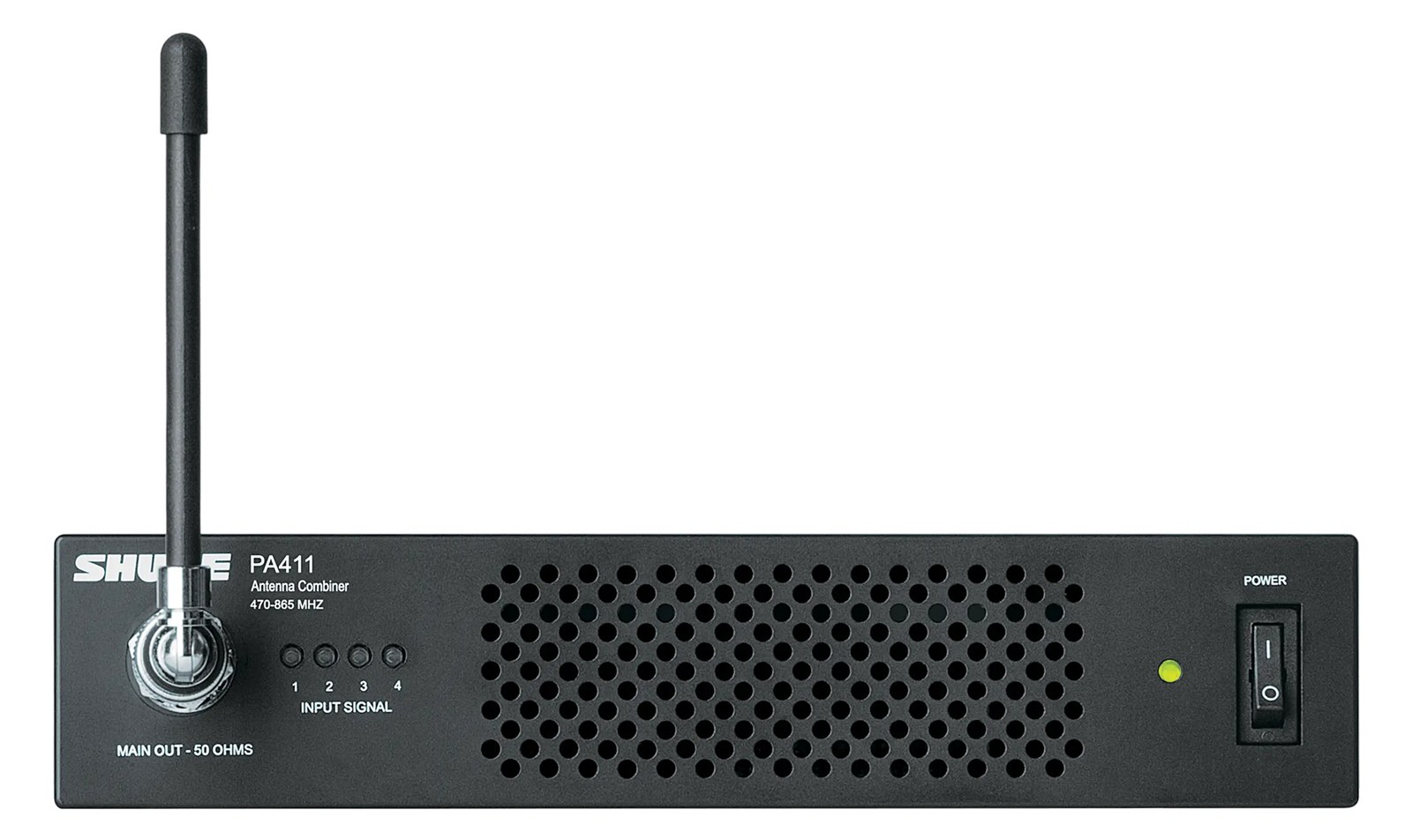
Shure PA411 Antenna Combiner
Shure·Model PA411·shure-pa411
Photos
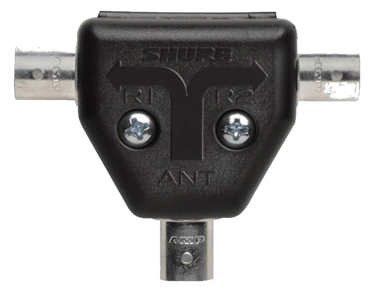
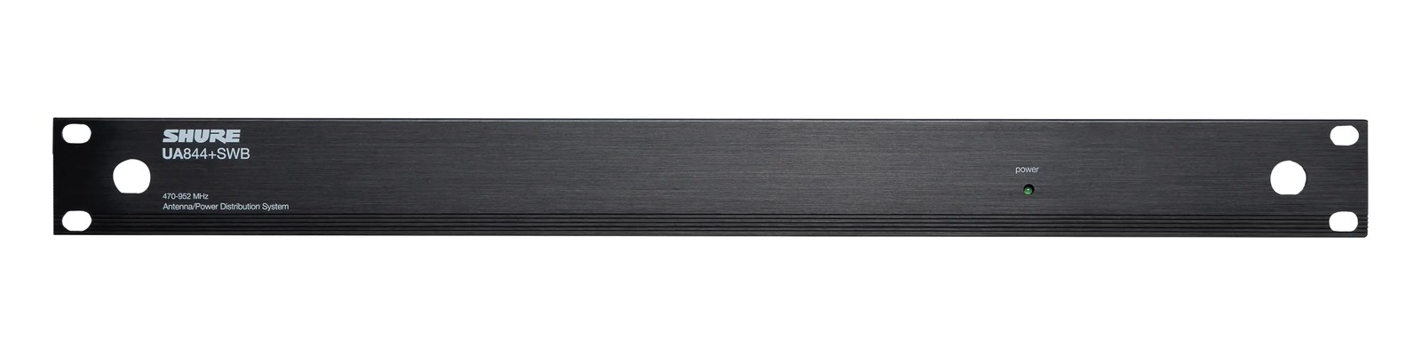
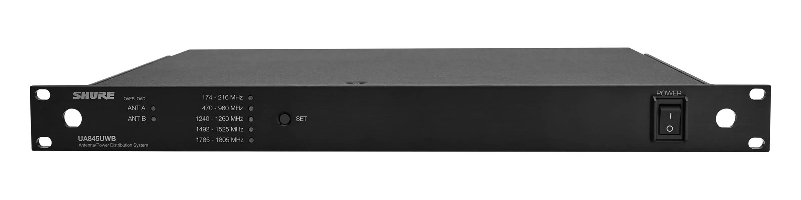
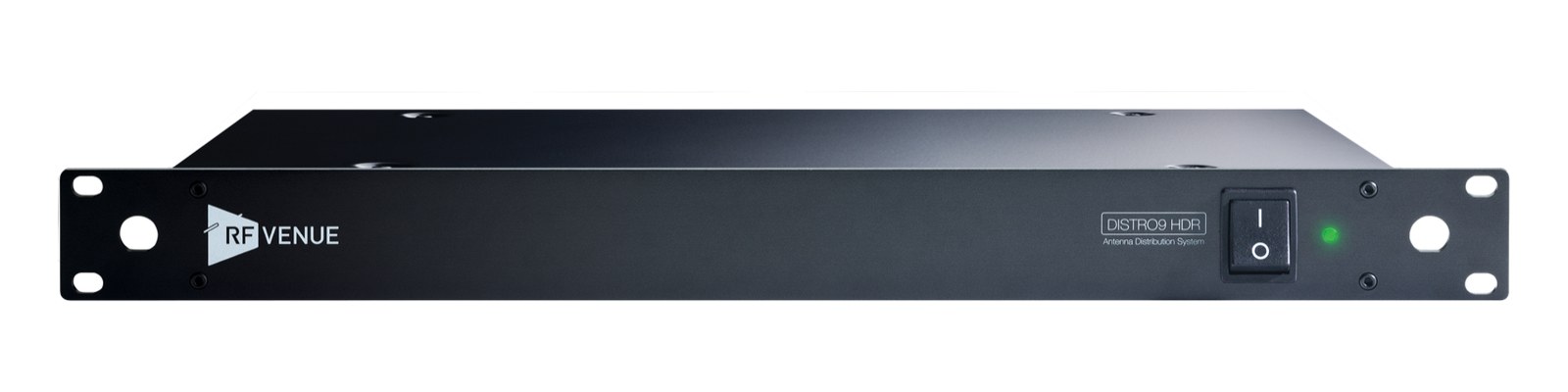
Manufacturer product photography — the drawn faceplate above stays true to panel layout; these show the hardware itself.
About the Shure PA411
The Shure PA411 combines the RFRadio Frequency — the wireless part of wireless. RF planning is why big rigs scan, coordinate, and combine antennas instead of hoping. from up to four PSM 300 transmitters onto a single antenna, cleaning up the intermodulationIntermodulation — ghost frequencies created when transmitters mix in each other’s electronics. Why multi-channel wireless is calculated, not guessed. and antenna farm that comes with stacking bodypack transmitters. It is the standard first upgrade for a multi-channel PSM 300 IEMIn-Ear Monitor — earpieces that replace floor wedges, feeding each player their own mix. The reason this whole rack exists. rack, feeding one PA805 directional antennaA directional antenna (paddle, LPDA, helical) aimed at the stage — focuses coverage where the performers are and rejects RF from elsewhere. instead of four whipsThe stock quarter-wave stick antenna that screws straight onto a receiver — fine for a channel or two in a small room. fighting each other. Half-rackThe standard slice of rack height: 1U = 1.75″. A 3U box takes three slices; half-rack gear pairs two units side by side in one. format mounts beside a fourth transmitter or on the included hardware.
The PA411 exists to solve a specific and familiar problem: you've stacked four PSM 300 transmitters in a rack, and now you have four whip antennasThe stock quarter-wave stick antenna that screws straight onto a receiver — fine for a channel or two in a small room. crowding the top of the case, coupling with each other, and generating intermodulationIntermodulation — ghost frequencies created when transmitters mix in each other’s electronics. Why multi-channel wireless is calculated, not guessed. products that show up as dropoutsA brief audio gap when the radio link fails — the thing diversity, distros, and coordination all exist to prevent. in the worst possible moments. The PA411 combines the RFRadio Frequency — the wireless part of wireless. RF planning is why big rigs scan, coordinate, and combine antennas instead of hoping. output of up to four PSM 300 transmitters onto a single antenna path, letting you feed one well-placed directional antennaA directional antenna (paddle, LPDA, helical) aimed at the stage — focuses coverage where the performers are and rejects RF from elsewhere. — typically a Shure PA805 or similar — instead of a cluster of omnis arguing with each other. It's a 1UThe standard slice of rack height: 1U = 1.75″. A 3U box takes three slices; half-rack gear pairs two units side by side in one. half-rack unit, so it pairs neatly with a fourth transmitter in the same rack space.
At 5 watts nominal draw and a shallow 150mm depth, the PA411 adds almost nothing to your rack's footprint or power budget. What it does add is RFRadio Frequency — the wireless part of wireless. RF planning is why big rigs scan, coordinate, and combine antennas instead of hoping. discipline. Running four transmitters through a single combined output means your antenna placement becomes intentional — you're aiming coverage rather than hoping four whipsThe stock quarter-wave stick antenna that screws straight onto a receiver — fine for a channel or two in a small room. average out to something useful. On a theater gig or a festival IEMIn-Ear Monitor — earpieces that replace floor wedges, feeding each player their own mix. The reason this whole rack exists. rig where the drive distance between the rack and the stage is real, the ability to run a single quality cable run to one directional antennaA directional antenna (paddle, LPDA, helical) aimed at the stage — focuses coverage where the performers are and rejects RF from elsewhere. is practically worth the unit's price on its own. The combinerThe transmit-side twin of a distro: merges several IEM transmitters into one antenna without letting them intermodulate. is active, so it requires power, but at under 8 watts worst case, any standard rack conditioner handles it without a second thought.
If you're running two or three PSM 300 channels and they're working fine, you probably don't need this yet. But the moment you hit four channels and start chasing intermittent dropoutsA brief audio gap when the radio link fails — the thing diversity, distros, and coordination all exist to prevent., or you're building a rig where the antenna has to be remote from the rack, the PA411 is the right answer and not an optional luxury. It's specifically designed for the PSM 300 ecosystem — don't assume it's a general-purpose combinerThe transmit-side twin of a distro: merges several IEM transmitters into one antenna without letting them intermodulate. for other transmitter families. If your rig is built around PSM 900s or a mixed-manufacturer system, check compatibility carefully before buying.
In the rack
- Mount the PA411 immediately above or below your PSM 300 transmitters so the TX In BNCThe twist-lock coax connector used for word clock and antenna runs — it locks, so it can’t be pulled out mid-show. runs are as short as possible — keep those internal cable runs under 30cm if you can.
- Feed the single Antenna Out to a directional antennaA directional antenna (paddle, LPDA, helical) aimed at the stage — focuses coverage where the performers are and rejects RF from elsewhere. like a PA805 positioned at the front edge of the stage, aimed at the performers. One aimed antenna outperforms four omnis pointed at the ceiling every time.
- The PA411 is half-rackThe standard slice of rack height: 1U = 1.75″. A 3U box takes three slices; half-rack gear pairs two units side by side in one., so pair it with a half-rack drawer or a fourth PSM 300 transmitter to fill the 1U slot cleanly — leaving a half-rack gap invites gear to shift during load-out.
- Label the TX In ports 1–4 with the corresponding transmitter channel at build time, not during soundcheck. BNCThe twist-lock coax connector used for word clock and antenna runs — it locks, so it can’t be pulled out mid-show. connectors all look identical under stage lighting.
4:1 active antenna combinerThe transmit-side twin of a distro: merges several IEM transmitters into one antenna without letting them intermodulate. for PSM 300 — one antenna for four transmitters.
I/O Ports (7)
| Port | Connector | Direction | Signal | Channels |
|---|---|---|---|---|
| TX 1 In | BNC | input | antenna | — |
| TX 2 In | BNC | input | antenna | — |
| TX 3 In | BNC | input | antenna | — |
| TX 4 In | BNC | input | antenna | — |
| Antenna Out | BNC | output | antenna | — |
- DC In (PS60) (DC BARREL)
- DC Out (PA411-PC) (DC BARREL)
Deciding between two?
Rack space, watts, weight and every connector, side by side.
Related gear


Related articles
Guides from our library that cover planning around antenna distro gear.
What an IEM rig actually is, the components that go into one, and how to plan your first one without overspending or blowing a circuit.
Why your wireless mics and IEMs need a frequency plan, what intermodulation means in practice, and how to coordinate channels for a clean show.
When you need a combiner vs a distro, active vs passive, cable choice and length math, and how to scale a 4-pack rig into an 8 or 12-pack without intermod nightmares.
How to build an IEM rack: choosing case size and depth, ordering gear by weight and heat, power sequencing rules, wiring practice, and a pre-show checklist.