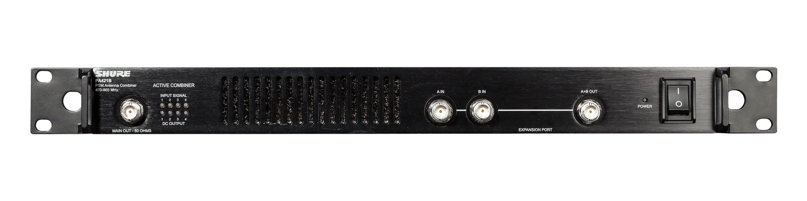
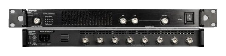
The Professional Wireless GX8 is the gold standard for antenna combining on major touring productions, trusted by RF coordinators worldwide. Its active filtering and combining circuitry handles eight IEM transmitter outputs while maintaining clean, intermod-free signal at the antenna. At 2U it takes more rack space than passive alternatives, but the filtering quality justifies it for large-scale shows where RF reliability is mission-critical.
~$4,995Use retailer rows for current price and stock
01 · What it does—and what that changes in your rig.
Product overview
Start with the payoff, then work through how it functions, where it fits, and the details that change a real build.
The payoff
Antenna Distro decisions, organized around the whole rig.
The GX8 is an active antenna combinerThe transmit-side twin of a distro: merges several IEM transmitters into one antenna without letting them intermodulate. built to solve one specific problem: you have eight IEMIn-Ear Monitor — earpieces that replace floor wedges, feeding each player their own mix. The reason this whole rack exists. transmitters and you need their RFRadio Frequency — the wireless part of wireless. RF planning is why big rigs scan, coordinate, and combine antennas instead of hoping. output consolidated onto a single antenna run — or in this case, two redundantA second copy of anything critical — supply, computer, network path — already running so one failure can’t stop the show. outputs — without those transmitters talking back into each other and generating intermodulationIntermodulation — ghost frequencies created when transmitters mix in each other’s electronics. Why multi-channel wireless is calculated, not guessed. products that kill your clean frequencies. Passive splitters can distribute antenna signals, but combining transmitter outputs passively is a different and nastier challenge. The GX8's active filtering circuitry is what makes it the go-to choice when RF coordinators on major touring productions need to trust their antenna infrastructure completely.
Documented outputs
22 destination connections
Documented inputs
9Based on documented inputs
Rack space
2UBuilder checks available rail space
Professional Wireless product panel2U · 20W
Function
How it works in the path
In practice, those two combined BNCThe twist-lock coax connector used for word clock and antenna runs — it locks, so it can’t be pulled out mid-show. outputs mean you can feed a main antenna position and a backup, or cover two zones of a large stage, from a single rack unitThe standard slice of rack height: 1U = 1.75″. A 3U box takes three slices; half-rack gear pairs two units side by side in one. managing all eight transmitter feeds. At 2U and 300mm deep, it fits a standard tour rack without drama, and 20 watts of draw is negligible. What matters at load-in is that the active filtering genuinely reduces the intermodIntermodulation — ghost frequencies created when transmitters mix in each other’s electronics. Why multi-channel wireless is calculated, not guessed. burden on your frequency coordinationCalculating a set of wireless frequencies that won’t interfere with each other or local TV — the homework behind a clean RF night. — you can run more channels in a tighter spectrum without the combinatorial RFRadio Frequency — the wireless part of wireless. RF planning is why big rigs scan, coordinate, and combine antennas instead of hoping. mess that passive or lower-quality active units produce. On a crowded festival stage where six other RF systems are fighting for space, that filtering margin is real and audible.
Best fit
Where it earns its place in the rack
If you're running eight IEMIn-Ear Monitor — earpieces that replace floor wedges, feeding each player their own mix. The reason this whole rack exists. transmitters on a major touring or festival rig and RFRadio Frequency — the wireless part of wireless. RF planning is why big rigs scan, coordinate, and combine antennas instead of hoping. cleanliness is non-negotiable, this is the unit. It earns its $4,995 price tag when the cost of a dropoutA brief audio gap when the radio link fails — the thing diversity, distros, and coordination all exist to prevent. or intermodIntermodulation — ghost frequencies created when transmitters mix in each other’s electronics. Why multi-channel wireless is calculated, not guessed. hit during a show is measured in reputation, not just dollars. If you're running four channels in a regional theater or a club where the RF environment is benign, a simpler combinerThe transmit-side twin of a distro: merges several IEM transmitters into one antenna without letting them intermodulate. or passive solution will serve you fine and leave budget for other things. The GX8 is tour-grade infrastructure — don't buy it to have it, buy it because your channel count and environment actually demand it.
In the rack
Details worth deciding before load-in.
Run your antenna cable from the GX8's Combined Out A to your primary antenna position first — treat Out B as a true hot spare feeding a secondary splitter or a physically offset antenna, not just a loop to a nearby passive.
Keep the GX8 away from your IEMIn-Ear Monitor — earpieces that replace floor wedges, feeding each player their own mix. The reason this whole rack exists. receivers in the rack if possible — even with its filtering, transmitter RFRadio Frequency — the wireless part of wireless. RF planning is why big rigs scan, coordinate, and combine antennas instead of hoping. this close to receiver front ends adds unnecessary noise floorThe constant background hiss a device produces on its own. Everything you pass through it sits on top — lower is better.. A rack unitThe standard slice of rack height: 1U = 1.75″. A 3U box takes three slices; half-rack gear pairs two units side by side in one. of separation or a shielded rack divider helps.
Label each BNCThe twist-lock coax connector used for word clock and antenna runs — it locks, so it can’t be pulled out mid-show. input with transmitter channel number and frequency at load-in using label tape; eight identical BNC connectors on the rear panel will cost you time during a hurried troubleshoot if they're anonymous.
The IECThe standard three-prong appliance power inlet on rack gear — the kettle lead. C13/C14 in spec-sheet speak. power inlet means it will share a standard rack power strip — just verify your distroOne pair of antennas feeding many receivers through an amplified splitter — replaces the forest of whips and keeps RF levels consistent. can handle the 25W max draw alongside your transmitters, receivers, and any powered antenna hardware on the same circuit.
02 · Know the whole path before you buy.
Signal path
Learn the route as a block diagram: source, product function, transport, and destination. Select any block to see what enters, what changes, and what leaves.
Interactive block diagramAuto-looping · hover, focus, or tap to hold a stage
Port-type signalProduct functionSystem boundary
Follow one signal from source to destination
Each block answers the same three questions: what arrives, what changes here, and what leaves.
01 · Source · selected
bnc + IEC C14
bnc
01 · Source
9 documented inputs
bnc + IEC C14
Arrives as
9 documented inputs
Connector
bnc + IEC C14
Signal
antenna
03 · What this product asks of the rest of the system.
Compatibility
Treat connector names as the start of the check—not the answer. These are the boundaries that determine a complete working path.
Best fit · Antenna Distro
Use it when 2U and 300 mm of depth fit the case.
Plan the companion path
Complete the path with upstream and downstream gear that matches connector, direction, signal type, protocol, and wiring standard.
Connector boundary
Documented connectors: bnc, IEC C14. Match connector, direction, and signal type—not shape alone.
04 · Every connector, grouped by job.
I/O ports
Switch the product view and the documented port inventory updates with it—hardware and data stay side by side.
Every connector, grouped by job.
Switch panels to keep the hardware view and the documented port list in sync.
Front panelRear panel
All documented ports for Professional Wireless GX8 Antenna Combiner
Port
Panel
Connector
Direction
Signal
Channels
Input 1
rear
bnc
input
antenna
—
Input 2
rear
bnc
input
antenna
—
Input 3
rear
bnc
input
antenna
—
Input 4
rear
bnc
input
antenna
—
Input 5
rear
bnc
input
antenna
—
Input 6
rear
bnc
input
antenna
—
Input 7
rear
bnc
input
antenna
—
Input 8
rear
bnc
input
antenna
—
Combined Out A
rear
bnc
output
antenna
—
Combined Out B
rear
bnc
output
antenna
—
Power (IEC)
rear
IEC C14
input
power
—
Showing 11 of 11 documented physical ports. Scroll to review the remaining rows.
05 · Compare the decision, not just the price.
Alternatives
The rows are organized around fit, power, I/O, and system role so a cheaper unit cannot hide a more expensive workflow.
GX8The Professional Wireless GX8 is the gold standard for antenna combining on major touring productions, trusted by RF coordinators worldwide. Its active filtering and combining circuitry handles eight IEM transmitter outputs while maintaining clean, intermod-free signal at the antenna. At 2U it takes more rack space than passive alternatives, but the filtering quality justifies it for large-scale shows where RF reliability is mission-critical.View gear →
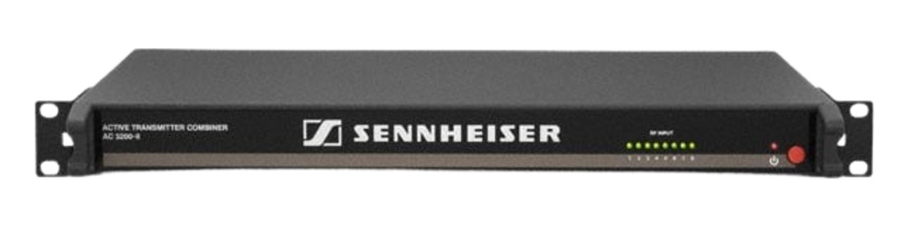
AC 3200-IIThe Sennheiser AC 3200-II is the touring-standard active combiner, putting up to eight IEM transmitters on a single antenna with headroom designed for high-power broadcast and arena use. Cascade ports let two units build a 16-channel system, and the robust RF stages keep intermod products down where cheaper combiners fold. If the monitor rack has a rack of SR 2050s in it, this is usually the box underneath them.View gear →
MAT288The Wisycom MAT288 is a top-tier antenna matrix that combines and distributes RF for both IEM transmitters and wireless mic receivers simultaneously in a single rack unit. This dual-purpose design eliminates the need for separate combiner and splitter units, saving significant rack space on large touring rigs. It is a premium investment that pays off when you are managing complex RF environments with many wireless channels across IEM and mic systems.View gear →
Placement is only the start. Builder checks space · depth · weight, power headroom, dependencies, and compatible signal paths around this exact catalog item.Open in Builder